Solar Collector

Inactive Publication Date: 2010-08-26
VKR HLDG AS
View PDF51 Cites 14 Cited by
  • Summary
  • Abstract
  • Description
  • Claims
  • Application Information

AI Technical Summary

Benefits of technology

[0011]The sloping surface can be countersunk in the casing so that the portion of the header projecting outwardly from the sloping surface does not protrude from the casing. Thus, the overall cross-sectional

Problems solved by technology

With in-roof collectors this type of construction is not possible, since a U-shaped flashing is disposed between neighboring collectors to ensure that water from precipitation will not reach the roof construction.
However, the downwardly projecting

Method used


Image

  • Solar Collector
  • Solar Collector
  • Solar Collector

Examples


Embodiment Construction

[0023]The preferred embodiment of the invention will be described specifically with reference to a flat plate collector assembly although it is understood that other absorber types may be employed with a minimum change in construction.

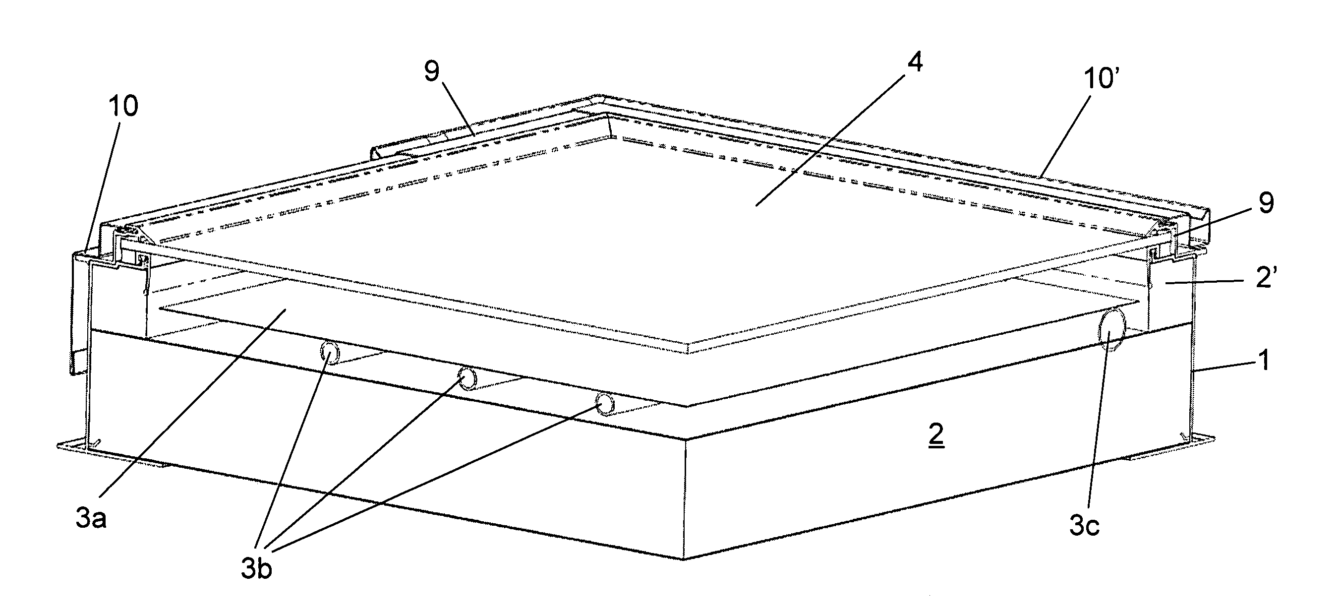
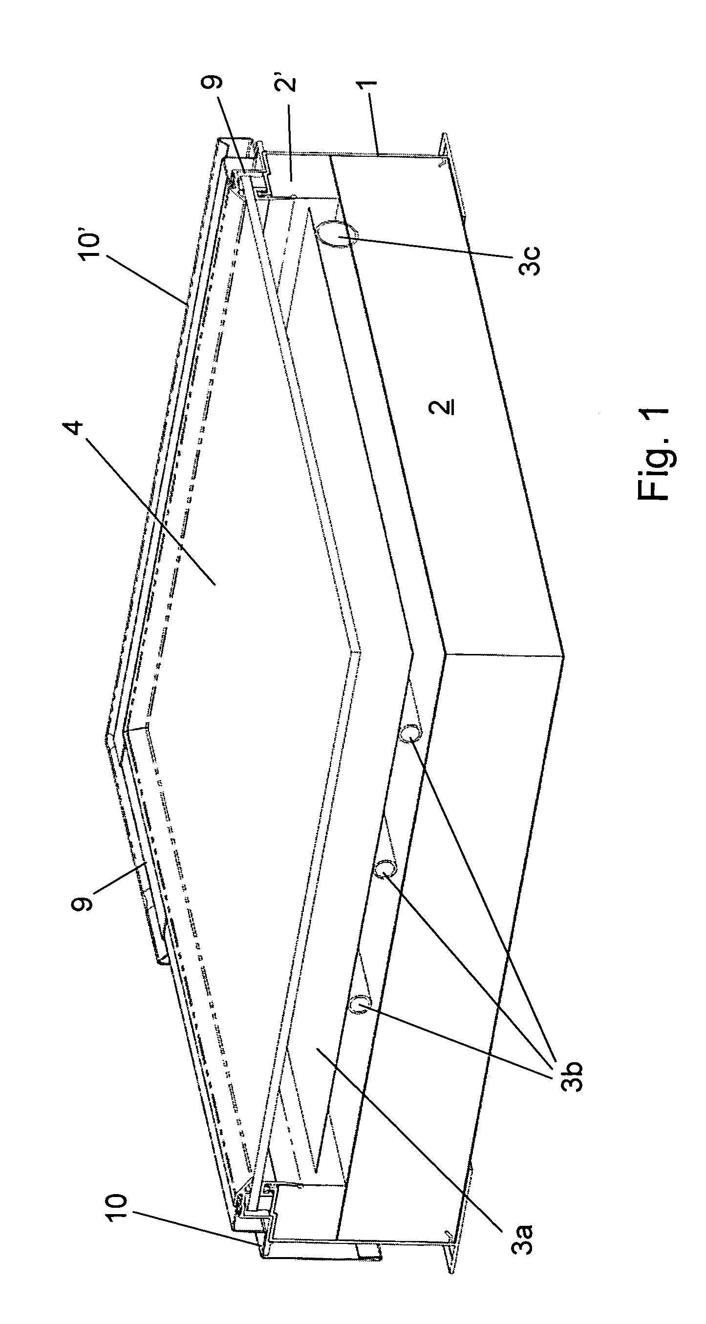
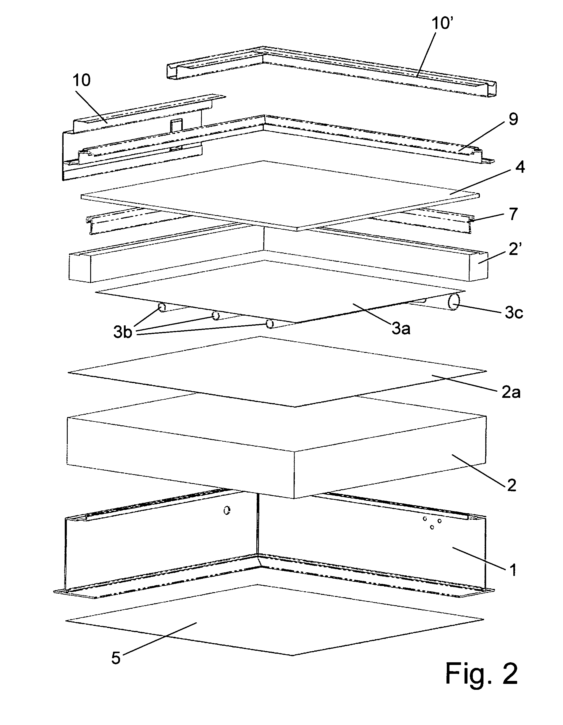
[0024]FIG. 1 shows by way of illustrative example a flat plate solar energy collector, whilst FIG. 2 is the corresponding exploded view. Seen in cutaway perspective view of FIGS. 1 and 2 the solar collector has a frame, an insulation layer 2, an absorber plate 3a and a cover pane 4. The frame, the insulation layer 2 and the cover pane 4 form a case with an enclosure. The enclosure is used to provide support for the absorber plate 3a, and to protect the collector from heat loss due to wind, plus the important function of keeping moisture from rain, snow and dew out of the collector.

[0025]The frame includes a backsheet 5 and outer side- and end panels 1. The insulation layer 2 is formed by a mat of mineral- or glass wool material, but could also be forme...


PUM


Abstract

A glazed solar collector with a frame surrounding an absorber (3a), an insulating layer (2) disposed beneath the absorber (3a) and a cover pane (4) spaced above the absorber (3a). Absorber tubing (3b) is connected to an supply header (15) and to an return header (16). The axis (X) of the supply/return header (15,16) is arranged at an angle to a plane (Z) coinciding with the cover pane (4) with the distance between the axis (X) and the plane (2) increasing along the axis (X) in a direction leading away from the collector.

Description

[0001]The present invention relates to glazed solar collectors and methods for producing such collectors. Such solar collectors typically have a rectangular frame containing an absorber, an insulating layer beneath the absorber, and a cover pane spaced above the absorber. The collectors are particularly suitable to be integrated into a pitched roof, but may also be installed on a flat roof by means of a mounting frame.BACKGROUND ART[0002]Numerous types of flat plate collector panel assemblies have been devised for solar installations. In flat plate collectors, customarily an absorber plate is deployed which is suitably comprised of steel, aluminum or copper plate coated with a mat black paint and characterized by its ability to absorb radiant energy and convert it to heat. The absorber plate is covered by a cover pane in order to reduce the heat loss from the plate without a corresponding reduction in the heat input due to the selective transmittance of the sun's rays by the glass o...

Claims


Application Information

Patent Timeline
IPC IPC(8): F24J2/46F24J2/50
CPCF24J2/4636F24J2/464Y02E10/40Y02B10/20F24J2/4647F24S40/80F24S80/30F24S80/40
Inventor MOLLER, BRENT
Owner VKR HLDG AS
Why Eureka
Try Eureka