Valve

a valve and valve body technology, applied in the field of valves, can solve the problems of increased signal loss in air gap, and difficulty in mwd tool operation, and achieve the effect of reducing the fluid flow ra

Active Publication Date: 2010-08-26
ANDERGAUGE
View PDF76 Cites 3 Cited by
  • Summary
  • Abstract
  • Description
  • Claims
  • Application Information

AI Technical Summary

Benefits of technology

[0011]The body may define a valve seat, and the valve seat may define a first area over which fluid pressure acts on the valve member when the valve member is in the closed position. The valve member may comprise a plug portion adapted for cooperating with the valve seat. In the open position the plug portion is preferably spaced from the valve seat, so reducing the pressure drop experienced by fluid flowing over the valve seat and reducing erosion. The plug portion may be elongate, and may have a tapered leading end for cooperating with the valve seat. A collar may define the valve seat. The body may define a larger second area over which a valve-opening fluid pressure may act when the valve member is in the open position, and fluid is flowing through the valve.
[0013]According to another aspect of the present invention there is provided a method of retaining a column of fluid in a tubular body, by providing a normally closed valve in a lower portion of a tubular body; flowing fluid through the valve to maintain the valve open, and at least reducing the fluid flow rate to allow the valve to close.
[0020]According to a still further aspect of the present invention there is provided a method of controlling flow through an elongate tubular body by pumping fluid through a tubular body at a first flow rate, the body comprising a fluid flow responsive member in a first configuration; and then increasing the fluid flow rate to produce a first fluid pressure differential across a first area to create a first actuating force, the first actuating force moving said member towards a second configuration, and with said member in the second configuration fluid flow at a higher second flow rate producing a lower second fluid pressure differential across a larger second area to create a larger second actuating force to maintain the member in the second configuration.

Problems solved by technology

Problems can be encountered when drilling if lost circulation drilling conditions are encountered; this is when a significant volume of drilling fluid is lost into permeable formations downhole.
A further problem associated with lost circulation occurs when the drilling fluid pumps are stopped; the fluid level in the annulus drops quickly as fluid is lost into the permeable formation and the level of fluid within the drill pipe also drops to equalise the fluid level (known as the U-tube effect).
This can create additional difficulties for the operation of MWD tools in such wells as, when the drilling fluid pumps are started again, the drill pipe must be filled with fluid before the MWD tool will start operating and sending signals to surface.
If the MWD tool starts operating before the pipe refills the signal is likely to be lost in the air gap.
Also, MWD tools can be damaged if they operate in the presence of a mixture of drilling fluid and gas.

Method used


Image

  • Valve
  • Valve
  • Valve

Examples


Embodiment Construction

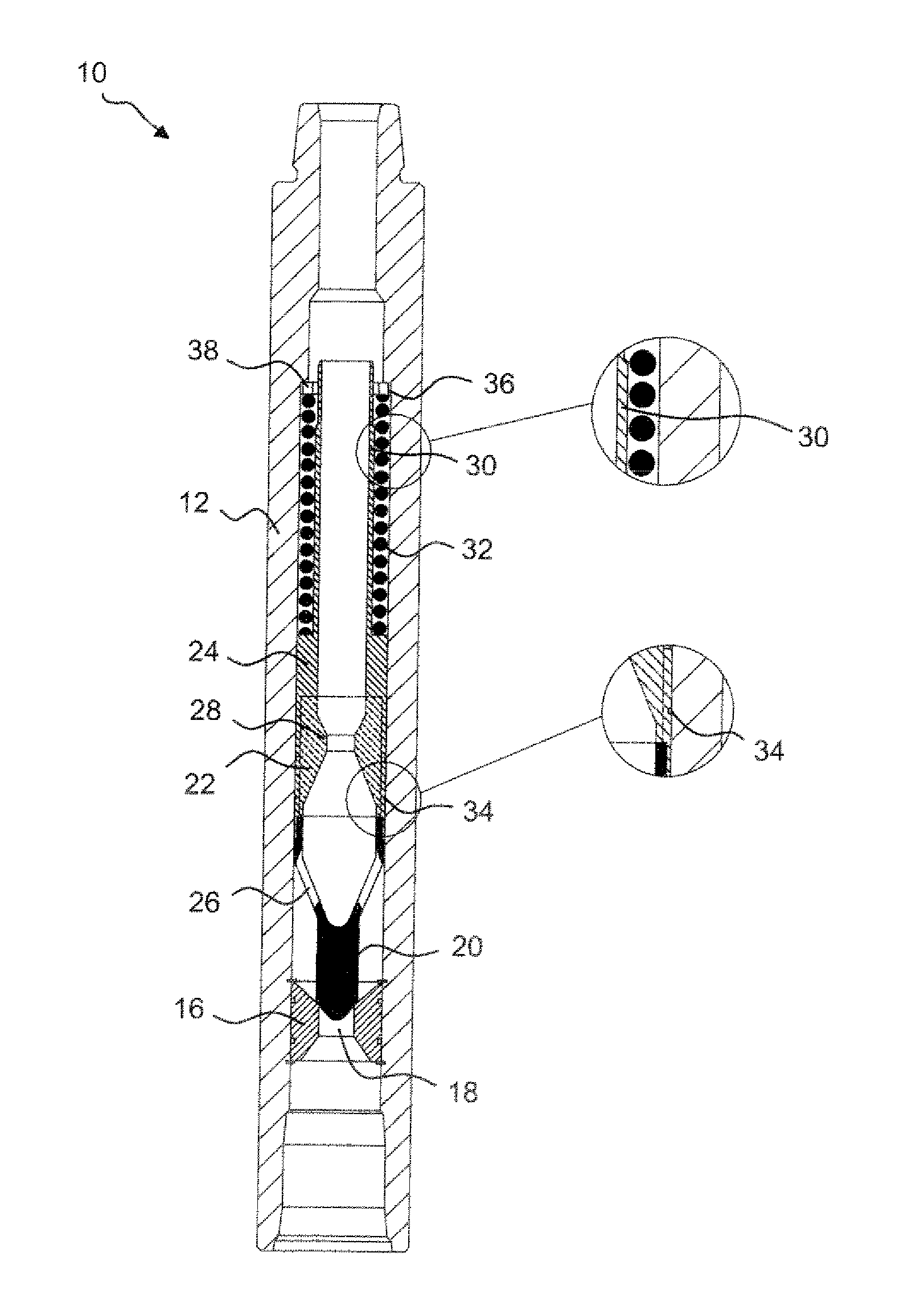
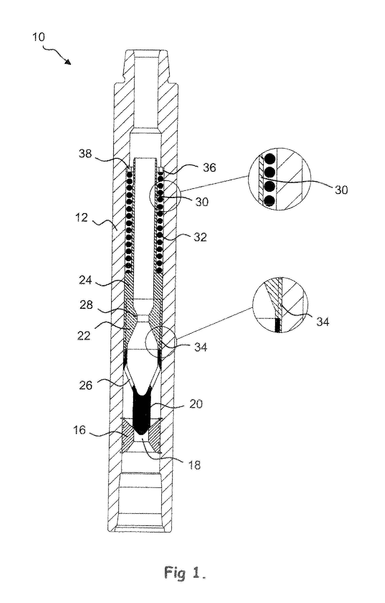
[0025]Reference is first made to FIG. 1 of the drawings which illustrates a valve, in the form of a downhole hydrostatic control valve 10, in accordance with a preferred embodiment of the present invention. FIG. 1 illustrates the valve in the closed configuration. The valve 10 comprises a tubular body 12 having ends adapted for coupling to drill pipe sections such that the valve 10 may be incorporated in a string of drill pipe. As will be described, in use the valve 10 is located in the lower end of a drill string and is designed to maintain the drill pipe full of fluid when the drilling fluid pumps are stopped but without an unacceptable increase in circulating pressure at higher flow rates.

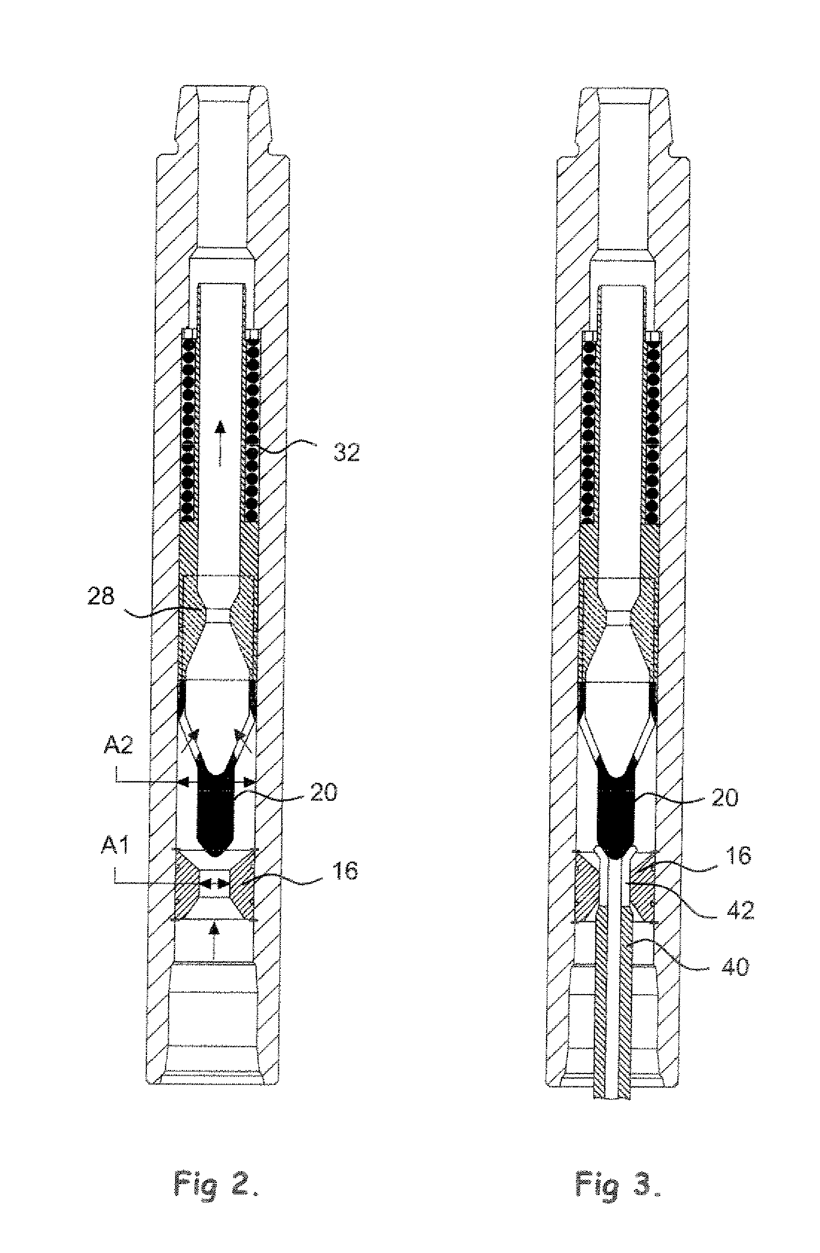
[0026]The body 12 contains a fixed valve seat 16 which defines a central through bore 18 of area A1 (FIG. 2). The valve seat 16 cooperates with a valve plug 20 forming part of a valve member 22 which is axially movable within the body 12 to control the opening and closing of the valve 10. The va...


PUM


Abstract

A downhole valve comprises a tubular body and a valve member. The valve member is normally closed and in the closed position may prevent or restrict passage of a working fluid through the body. The valve member is movable to an open position, a first working fluid pressure differential being necessary to move the valve member from the closed position and a lower second working fluid pressure differential being necessary to maintain the valve member in the open position.

Description

CROSS REFERENCE TO RELATED APPLICATIONS[0001]This application is a continuation of pending U.S. patent application Ser. No. 11 / 813,439 filed on Sep. 4, 2008, which is a United States national stage filing of PCT International Patent Application No. PCT / GB2006 / 000124 filed on 16 Jan. 2006 which claims priority from GB Application No. 0500713.3 filed 14 Jan. 2005.FIELD OF THE INVENTION[0002]This invention relates to a valve, and in particular but not exclusively to a downhole valve, and most particularly to a hydrostatic control valve.BACKGROUND TO THE INVENTION[0003]In the oil and gas exploration and production industry, subsurface hydrocarbon-bearing formations are accessed by drilling bores from surface. In a typical drilling operation a drill bit is mounted on the lower end of a tubular string of pipe extending from surface. Drilling fluid or “mud” is pumped down the drill pipe string from surface and exits through jetting nozzles in the drill bit. The drilling fluid serves a numb...

Claims


Application Information

Patent Timeline
Patent Type & Authority Applications(United States)
IPC IPC(8): E21B34/06F17D3/00
CPCE21B34/06Y10T137/7783Y10T137/7839Y10T137/0379
Inventor EDDISON, ALAN MARTYNFARQUHAR, HAZEL
Owner ANDERGAUGE
Why Eureka
Try Eureka