Multi-cyclone sediment filter

a sediment filter and multi-cyclone technology, applied in the direction of filtration separation, moving filter element filter, sediment separation with centrifugal force, etc., can solve the problem that the separation element does not allow the denser material, the operation parameters of the equipment are susceptible to changes, and the apparatus is down time and the amount of inventory needed. problems, to achieve the effect of saving thousands of gallons of water, high fluid flow, and rapid fluid processing

Active Publication Date: 2010-08-26
WATERCO
View PDF11 Cites 33 Cited by
  • Summary
  • Abstract
  • Description
  • Claims
  • Application Information

AI Technical Summary

Benefits of technology

[0019]It is an object of the present invention to provide a new and improved multi-cyclone sediment filter that provides effective filtering for small or large applications for filtering swimming pool water, waste water, and oil.
[0020]It is another object of the present invention to provide a new and improved sediment filter that is easily repaired, maintained, cleaned, and serviced.
[0022]An even further object of the present invention is to provide a novel multi-cyclone sediment filter that includes a plurality of radially disposed cyclonic cones that allows for high fluid flows and rapid fluid processing.
[0023]Still another object of the present invention is to provide a multi-cyclone separator that eliminates the need for frequent back flushing of swimming pool sand filters, thus saving thousands of gallons of water.

Problems solved by technology

The conical shape of the separator elements does not allow the denser material to exit the top of the inverted cone.
This increases apparatus down time and the amount of inventory needed to maintain the system in working order.
It has been recognized that all of these elements are all susceptible to changes in operational parameters.
Typically, however, the parameters do not remain constant.
In many respects, this is difficult to distinguish over Tashiro et al.

Method used


Image

  • Multi-cyclone sediment filter
  • Multi-cyclone sediment filter
  • Multi-cyclone sediment filter

Examples


Embodiment Construction

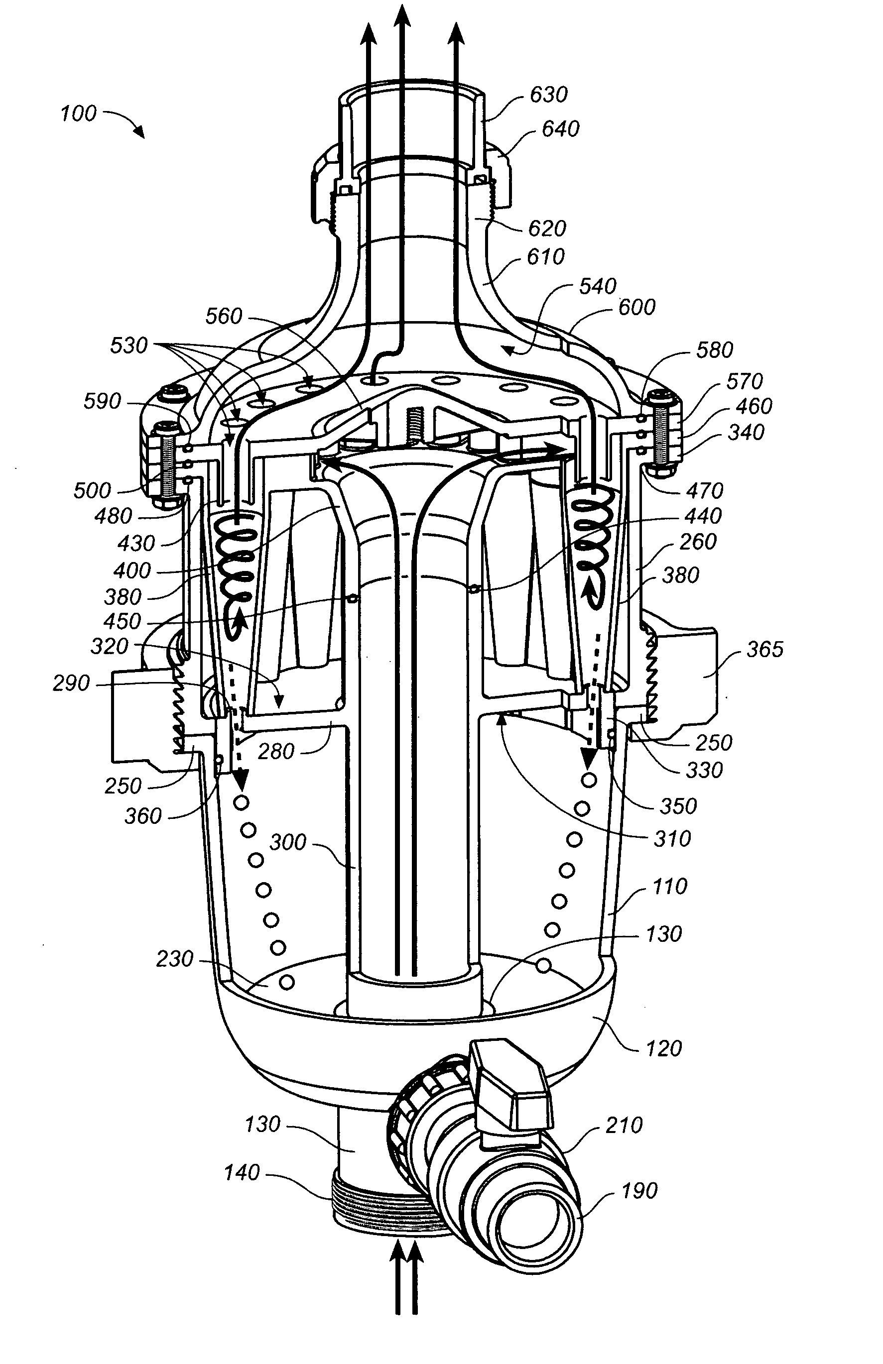
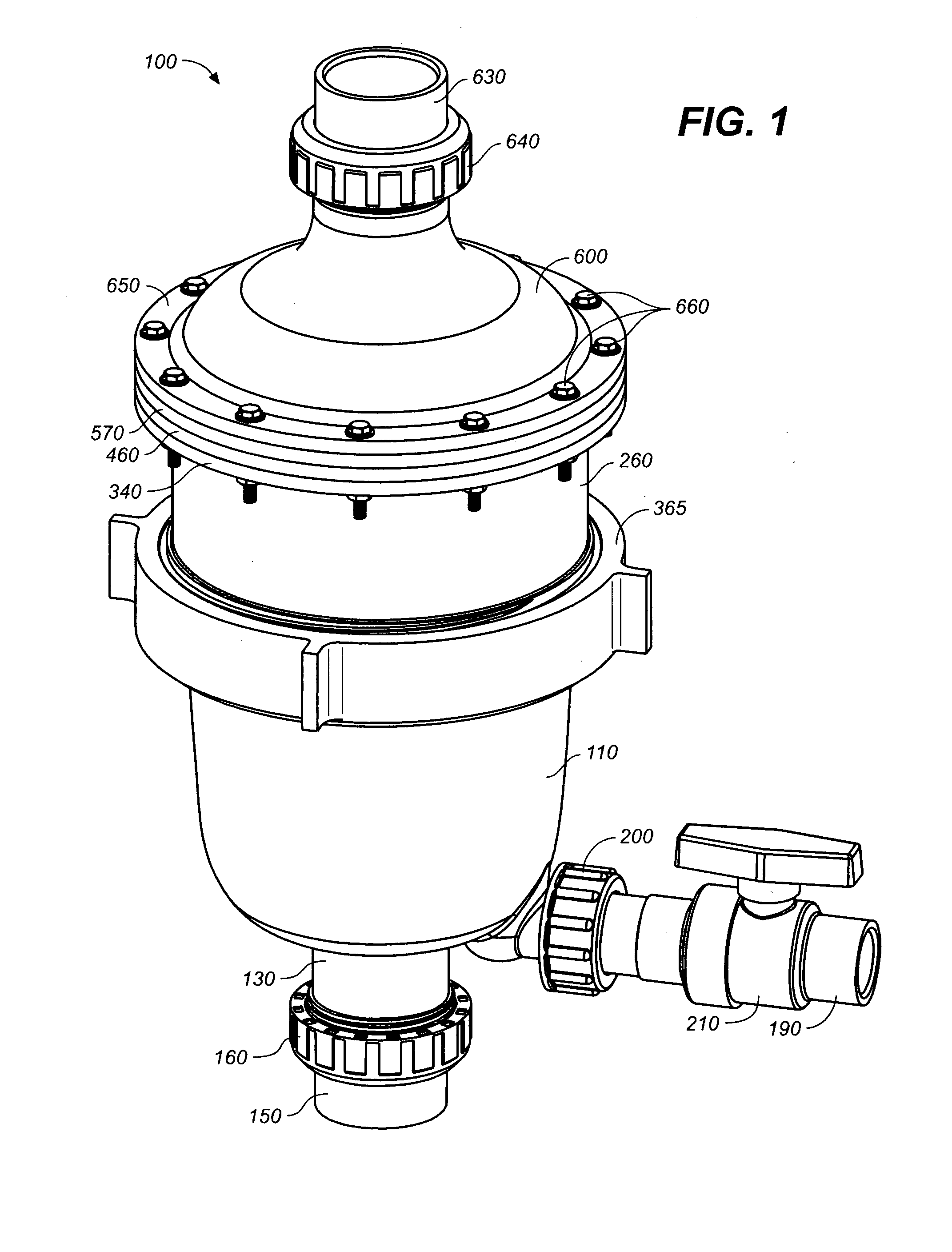
[0089]Referring to FIGS. 1 through 3, wherein like reference numerals refer to like components in the various views, there is illustrated therein a new and improved multi-cyclone separator or sediment filter, generally denominated 100 herein. Collectively these views show that the inventive apparatus comprises a lower sediment bowl 110 having a hemispherical bottom portion, or sump, 120, with a fluid inlet 130, preferably a tube axially disposed on the central axis A through the bottom. The fluid inlet includes a threaded male end 140 which is connected to a pressurized fluid source through a fluid source tube 150 via a locking collar 160 having female threads complementary to the male end of the fluid inlet tube.

[0090]Extending radially from the bottom portion of the sediment bowl is a sediment bowl drain tube 170 having a threaded male end 180 for connection to a drain outlet pipe 190 via a locking collar 200. The drain outlet pipe preferably includes a purge valve 210 for selecti...


PUM

PropertyMeasurementUnit
pressureaaaaaaaaaa
outer diameteraaaaaaaaaa
diameteraaaaaaaaaa

Abstract

A multi-cyclone sediment filter having a sediment bowl with a hemispherical bottom and a sump for collecting sediment, a cylindrical cyclone housing disposed above and sealingly connected to the sediment bowl, a removable and replaceable cyclone cartridge inserted into the cyclone housing, a diffuser plate sealingly connected to the cyclone cartridge and cyclone housing, a fluid inlet for introducing fluid into the cyclone housing, and a fluid outlet for discharging fluid from the cyclone housing. The cyclone cartridge inserted in the cyclone housing includes a plurality of vertically disposed inverted cone-shaped fluid cyclones, each having a small opening at a lower end and larger opening at an upper end. The cartridge has a plurality of fluid flow paths that direct fluid to the cyclones where a vortex is induced in the moving fluid. As sediment is removed from the fluid in each cyclone, it is separated out and delivered down into the sediment bowl sump, while fluid is directed upwardly and out to the fluid outlet.

Description

BACKGROUND OF THE INVENTION[0001]1. Technical Field[0002]The present invention relates generally to cyclonic separators, more particularly to a multi cyclone separator and sediment filter for fluids, utilizing a plurality of cyclone apparatus arranged in a radial pattern to remove particulate debris from the fluid.[0003]2. Background Art[0004]Cyclonic separators are used for separating unwanted debris from fluids by using centrifugal force. The fluid is typically injected obliquely into the cyclonic separator elements such that a circular flow is set up. The centrifugal forces act on the debris, which is more dense than the fluid in which it is suspended, forcing the denser material outwardly and toward the perimeter of the separation chamber. The conical shape of the separator elements does not allow the denser material to exit the top of the inverted cone. Instead, the substantially debris-free fluid surrounding the center of the vortex is extracted and re-circulated, while the de...

Claims


Application Information

Patent Timeline
Patent Type & Authority Applications(United States)
IPC IPC(8): B01D21/26
CPCB04C5/04B04C5/12B04C5/28B04C5/185B04C5/14
Inventor TANDON, PRADEEP KUMAR
Owner WATERCO
Why Eureka
Try Eureka