Welding methods and systems

a welding method and system technology, applied in the field of arc welding, can solve the problems of adverse effects of welding techniques, adverse effects of welding on the other side, and puddles on the other side, and achieve the effects of facilitating uniform controllable weld penetration, shape and size, and facilitating the creation of consistent high-quality welds

Inactive Publication Date: 2010-08-26
LINCOLN GLOBAL INC
View PDF8 Cites 69 Cited by
  • Summary
  • Abstract
  • Description
  • Claims
  • Application Information

AI Technical Summary

Problems solved by technology

Due to the concurrent welding, however, the high heat and magnetic field from the arc on one side of the joint will often adversely affect the arc and weld puddle on the other side.
Other concurrent welding techniques exhibit the same difficulties with respect to the effect of using multiple arcs where one arc adversely affects the other arc.
For example, where the work piece is grounded along a common axis, as in a tank welding application, the use of two arcs welding the ends of the tank concurrently often exhibit the same adverse affects.
Again, operating the arcs simultaneously often leads to adverse affects.
As a related issue, in welding such joints, it is difficult to obtain good penetration of the weld.
Often, adequate penetration may be achieved but requires multiple passes making the weld somewhat inefficient in terms of the amount of material used and the time and energy necessary to achieve suitable penetration.

Method used


Image

  • Welding methods and systems
  • Welding methods and systems
  • Welding methods and systems

Examples


Embodiment Construction

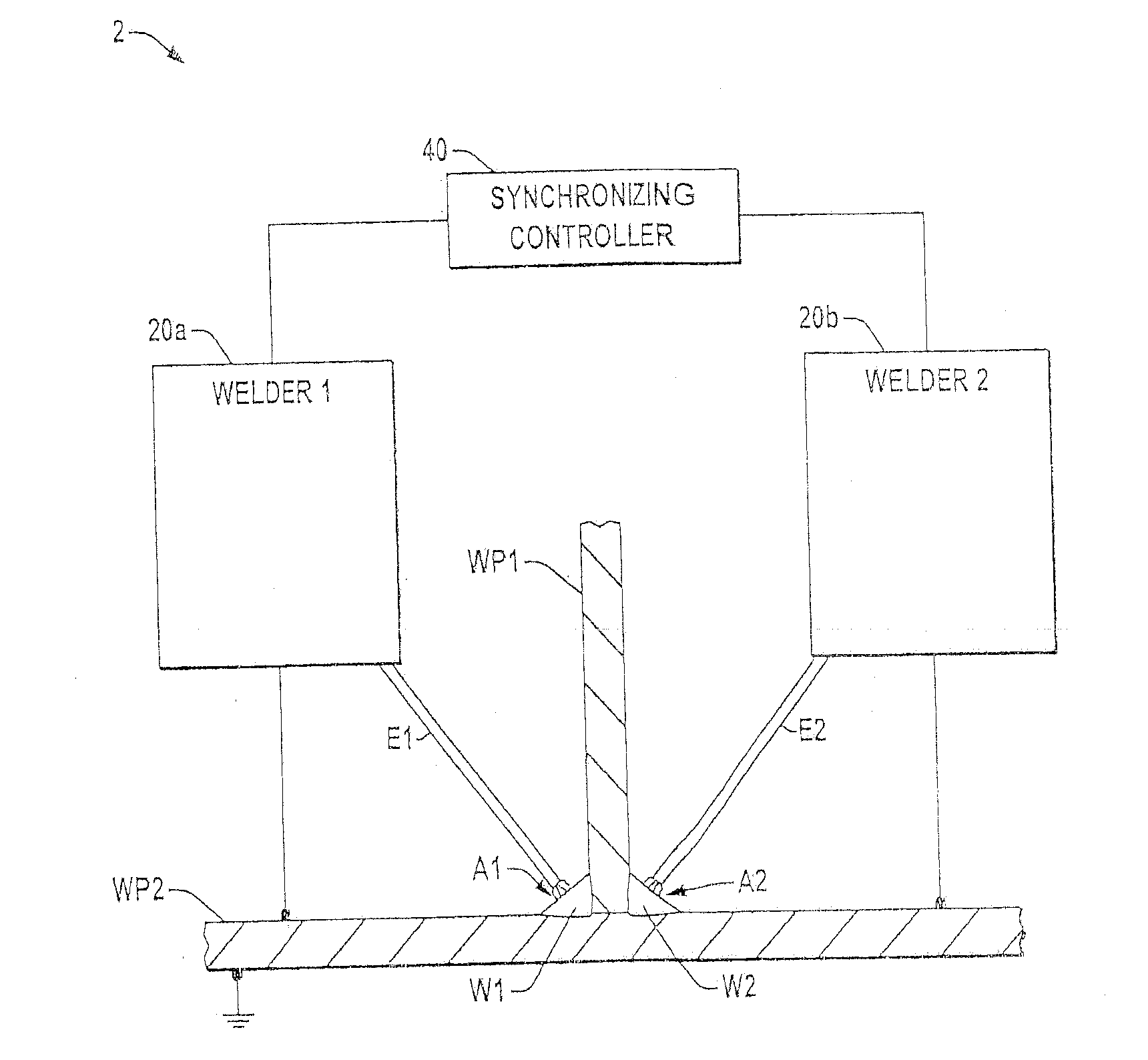
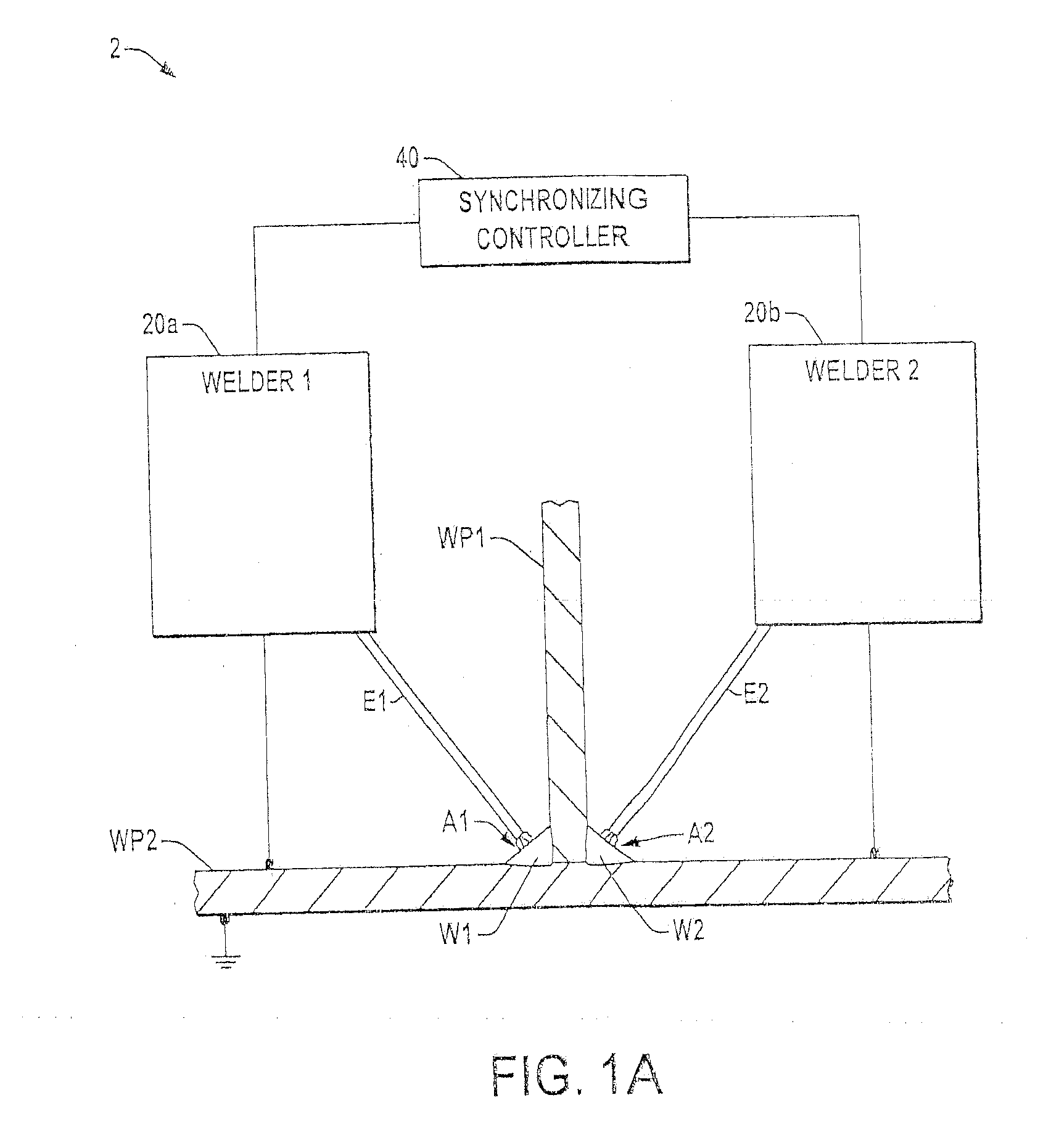
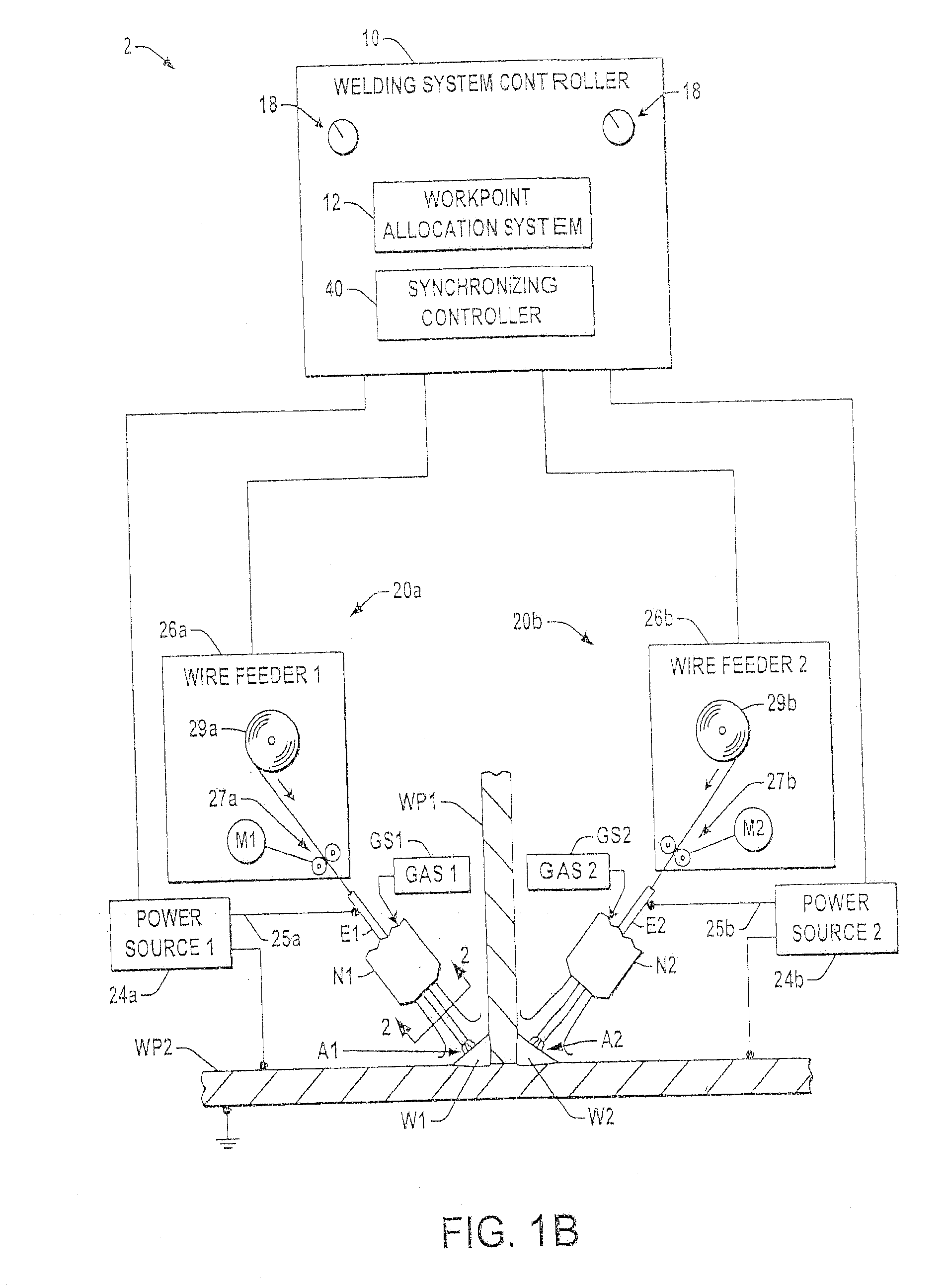
[0046]Referring now to the figures, several embodiments or implementations of the present invention are hereinafter described in conjunction with the drawings, wherein like reference numerals are used to refer to like elements throughout and wherein the illustrated structures are not necessarily drawn to scale. Although several preferred embodiments are illustrated and described hereinafter in the context of root pass dual fillet welding using two welding electrodes positioned on opposite sides of a welded work piece, other embodiments are possible in which two or more pairs of opposing welding electrodes are used in creating a dual fillet weld with one or more passes, with the waveforms applied to the electrodes and / or the work points used by opposing welding machines of a given pair being operated in a synchronized manner to provide controlled waveform and / or work point phase angles during concurrent creation of two fillet welds. Further embodiments are also contemplated in which ...


PUM

PropertyMeasurementUnit
angleaaaaaaaaaa
angleaaaaaaaaaa
phase angleaaaaaaaaaa

Abstract

A welding system is provided, in which two electrodes are directed at a joint between two work pieces and the electrodes are energized with DC pulse or AC welding waveforms at a controlled waveform phase angle. The systems include a synchronizing controller to synchronize the welding waveforms, and a work point allocation system provides one or more work point values to the welding machines to provide synergic control of the welding according to a user selected system work point value or parameter. The systems and methods further provide for synchronized work point value modulation for the opposite sides of a dual fillet weld. The system and method further provide a high energy heat source that directs intense heat at a portion of the weld joint to improve weld penetration.

Description

CROSS REFERENCE TO RELATED APPLICATIONS[0001]This U.S. patent application is a continuation-in-part (CIP) application of U.S. patent application Ser. No. 11 / 457,609 filed on Jul. 14, 2006, of which is hereby incorporated herein by reference.TECHNICAL FIELD OF THE INVENTION[0002]The present invention relates generally to arc welding, and more particularly to methods and systems for creating welds using synchronized welding waveforms and modulated work points.BACKGROUND OF THE INVENTION[0003]In welding fabrications, the “T” connection or T-joint is one of the most common welded connections used to join two pieces of metal together, in which a first piece of metal such as a stiffener work piece forms the leg of the T and the second work piece is the top of the T. Often, both corners of the T connection are welded with fillet welds, wherein these weld joints are referred to as “dual fillet” welds. In some applications, the joint is long and straight and the welding can be mechanized wit...

Claims


Application Information

Patent Timeline
Patent Type & Authority Applications(United States)
IPC IPC(8): B23K26/20B23K9/10
CPCB23K26/0676B23K26/1429B23K26/243B23K28/02B23K2201/18B23K26/0604B23K9/025B23K9/092B23K9/1043B23K9/1735B23K2201/28B23K26/242B23K26/348B23K2101/18B23K2101/28
Inventor PETERS, STEVEN R.
Owner LINCOLN GLOBAL INC
Why Eureka
Try Eureka