Full-width Line Image-sensing Head

a full-width line, image-sensing head technology, applied in the field of electromechanical imaging, can solve the problems of inability to achieve f- compensation, inability to detect the loss of imaging light intensity near the edge of the object plane, etc., to achieve the effect of reducing the level of image signal and signal-to-noise ratio (s/n)

Inactive Publication Date: 2010-08-26
CMOS SENSOR
View PDF2 Cites 20 Cited by
  • Summary
  • Abstract
  • Description
  • Claims
  • Application Information

AI Technical Summary

Benefits of technology

[0010]b) A full-width linear rod lens (FLRL) of length LRL along the X-direction and displaced from the PLI in the Z-direction by a working distance DWKG with DWKG<DIMG. Therefore the FLRL is located between the PLI and the FLIS. Where LRL is about equal to LPL and DWKG

Problems solved by technology

Given the imaging geometric parameters involved the Oblique Angle θ can become as large as 60 to 70 degrees where the degree of f-θ compensation can become unacceptable even with an expensive f-θ Focusing Lens.
Such a loss of imaging light intensity near the edge of the object plane is most likely unacceptable in that

Method used


Image

  • Full-width Line Image-sensing Head
  • Full-width Line Image-sensing Head
  • Full-width Line Image-sensing Head

Examples


Embodiment Construction

[0035]The description above and below plus the drawings contained herein merely focus on one or more currently preferred embodiments of the present invention and also describe some exemplary optional features and / or alternative embodiments. The description and drawings are presented for the purpose of illustration and, as such, are not limitations of the present invention. Thus, those of ordinary skill in the art would readily recognize variations, modifications, and alternatives. Such variations, modifications and alternatives should be understood to be also within the scope of the present invention.

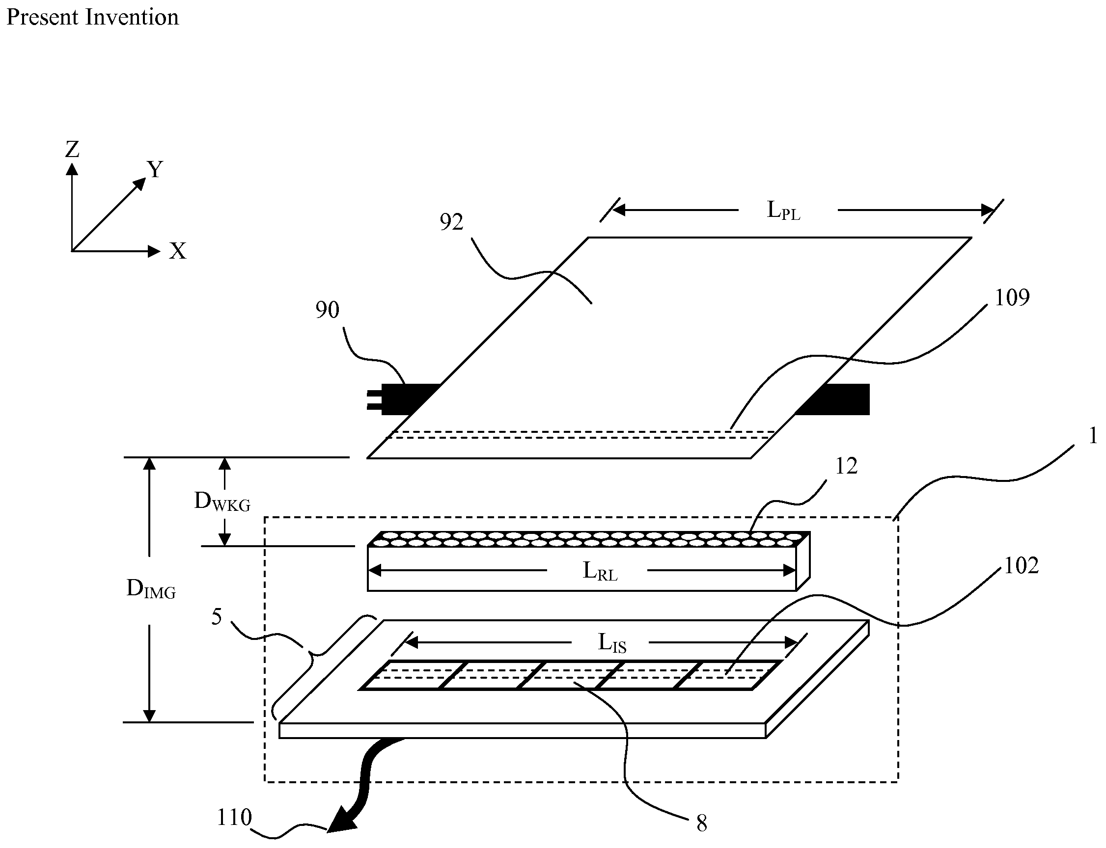
[0036]FIG. 1 illustrates the present invention full-width line image-sensing head (FLIH) 1 for converting a pixel line image (PLI) 109 of length LPL along the X-direction into a corresponding line image signal (LIS) 110. The pixel line image (PLI) 109 is part of an object plane 92 made visible by an illumination source 90 located nearby and oriented along the X-direction.

[0037]The FLIH ...


PUM


Abstract

A full-width line image-sensing head (FLIH) is proposed for, expressed in X-Y-Z coordinates, converting a pixel line image (PLI) of length LPL along X-direction into a line image signal (LIS). The FLIH includes a full-width linear image sensor (FLIS) of length LIS along X-direction and displaced from the PLI along Z-direction by an imaging distance DIMG for converting an incident line image (ILI) impinging upon its FLIS top surface into the LIS. Where LIS is about equal to LPL. The FLIH also has a full-width linear rod lens (FLRL) of length LRL along X-direction and displaced from the PLI in Z-direction by a working distance DWKG. Where LRL is about equal to LPL and DWKG is selected such that the PLI gets focused by the FLRL into the ILI at the FLIS top surface with an imaging magnification factor of about 1:1.

Description

BACKGROUND OF THE INVENTION[0001]1. Field of the Invention[0002]The present invention relates to electronic imaging. More particularly, the present invention is related to an I-CIS (Industrial Camera Image Scanner) such as used for large flat panel inspection.[0003]2. Related Background Art[0004]A prior art camera image scanner configuration for industrial application is illustrated in Fig. A. Such industrial application includes, for example, the real-time inspection of large liquid crystal display (LCD) production panels, thin film solar panels and textile production webs. Here, an object surface located in an object plane is, while being illuminated by an Illumination Source, imaged by a charge coupled device (CCD) Image Sensor located at an “Imaging Distance” away from the object plane (along Z-direction). While not specifically illustrated here, to those skilled in the art areal inspection of the object surface can be accomplished by imaging the object surface on a scan-line by...

Claims


Application Information

Patent Timeline
IPC IPC(8): H01L31/0232
CPCG01N21/8903G01N21/9501G01N2021/9513H04N1/1935H04N1/0312H04N1/1934H04N1/02845
Inventor WANG, WENG-LYANGLIN, SHENGMINLIN, CHI-PINHSIAO, FENG KE
Owner CMOS SENSOR
Why Eureka
Try Eureka