Vehicle body floor structure

a technology for vehicle body and floor, which is applied in the direction of roofs, electric propulsion mounting, transportation and packaging, etc., can solve the problems of increasing the overall weight of the vehicle body, affecting the service life of the vehicle, so as to achieve the effect of effectively dispersing such an external input force and ensuring the safety of the functional componen

Inactive Publication Date: 2010-08-26
HONDA MOTOR CO LTD
View PDF1 Cites 61 Cited by
  • Summary
  • Abstract
  • Description
  • Claims
  • Application Information

AI Technical Summary

Benefits of technology

[0011]In view of the foregoing prior art problems, it is an object of the present invention to provide an improved vehicle body floor structure which can reliably protect a functional component, disposed within a floor tunnel provided on a laterally central portion of the vehicle body, from an external input force, such as a load caused by a side collision of the vehicle, and can effectively disperse such an external input force.
[0013]The passageway extending through the stored component in the width direction of the vehicle body may be changed in position in the front-rear direction of the vehicle body so that the cross member can be placed or set at a desired position. In this way, the cross member can be set at a suitable position (load input position) to which a load applied from a side of the vehicle can be efficiently transmitted. As a consequence, the present invention can eliminate a need to increase reinforcement of the vehicle body and thereby reduce the weight of the vehicle body.
[0014]Further, because the stored component is supported in a substantially floating manner within the floor tunnel by being supported on the cross member via the resilient member, an assembly error can be effectively absorbed, which can thereby facilitate positioning of the cross member relative to the inner surfaces of the opposed side walls of the floor tunnel at the time of assembly. In addition, when a side collision load is input to the cross member, the side collision load can be effectively prevented from acting on the stored component that is supported in a substantially floating manner within the floor tunnel.
[0017]Preferably, the cross member supports the stored component via a stay member that is supported, via the resilient member, in a substantially floating manner within the floor tunnel. Thus, the stored component can be mounted (sub-assembled) to the cross member in advance, which allows the cross member and stored component to be assembled to the vehicle body with an increased ease.
[0018]Preferably, the cross member is fixed at the opposite ends to horizontal bracket bottom surfaces each projecting in a substantially right-angled triangular shape from the inner surface of a corresponding one of the opposed side walls of the floor tunnel. Thus, the cross member can be fixedly fastened to the floor tunnel from below, which can significantly enhance mounting operability of the cross member.
[0019]Preferably, the stay member is provided in perpendicularly intersecting relation to the cross member. This arrangement can stably support the stored component that is, for example, elongated in the front-rear direction of the vehicle body. Alternatively, the stay member may be provided in parallel relation to the cross member.

Problems solved by technology

Environment-friendly vehicles have come to the front in recent years, but these vehicles are more complicated in structure than ordinary vehicles.
Further, equipment mounted on the environment-friendly vehicles tends to be great in size.
However, in this case, the functional component 222 itself tends to be great in weight, which would lead to an increased overall weight of the vehicle body.
However, when a load has been applied from a side of the vehicle body, the functional components 232 fixed to the partition wall 234 may also be undesirably dragged so that there would occur a possibility of the functions of the components 232 being impaired.

Method used


Image

  • Vehicle body floor structure
  • Vehicle body floor structure
  • Vehicle body floor structure

Examples


Embodiment Construction

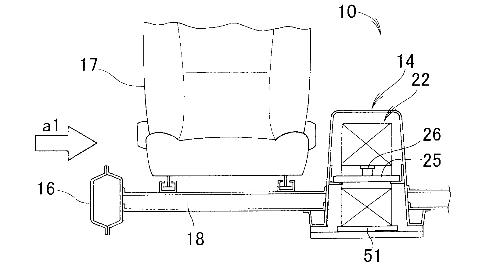
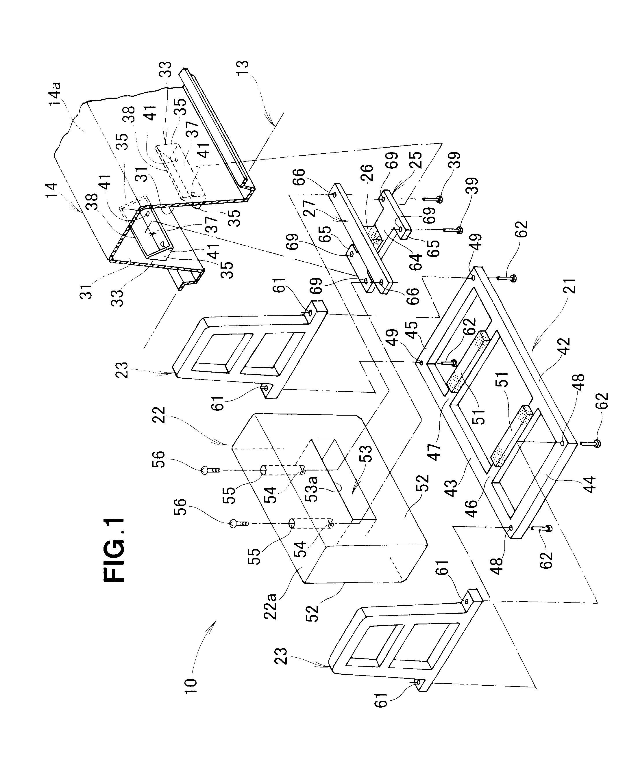
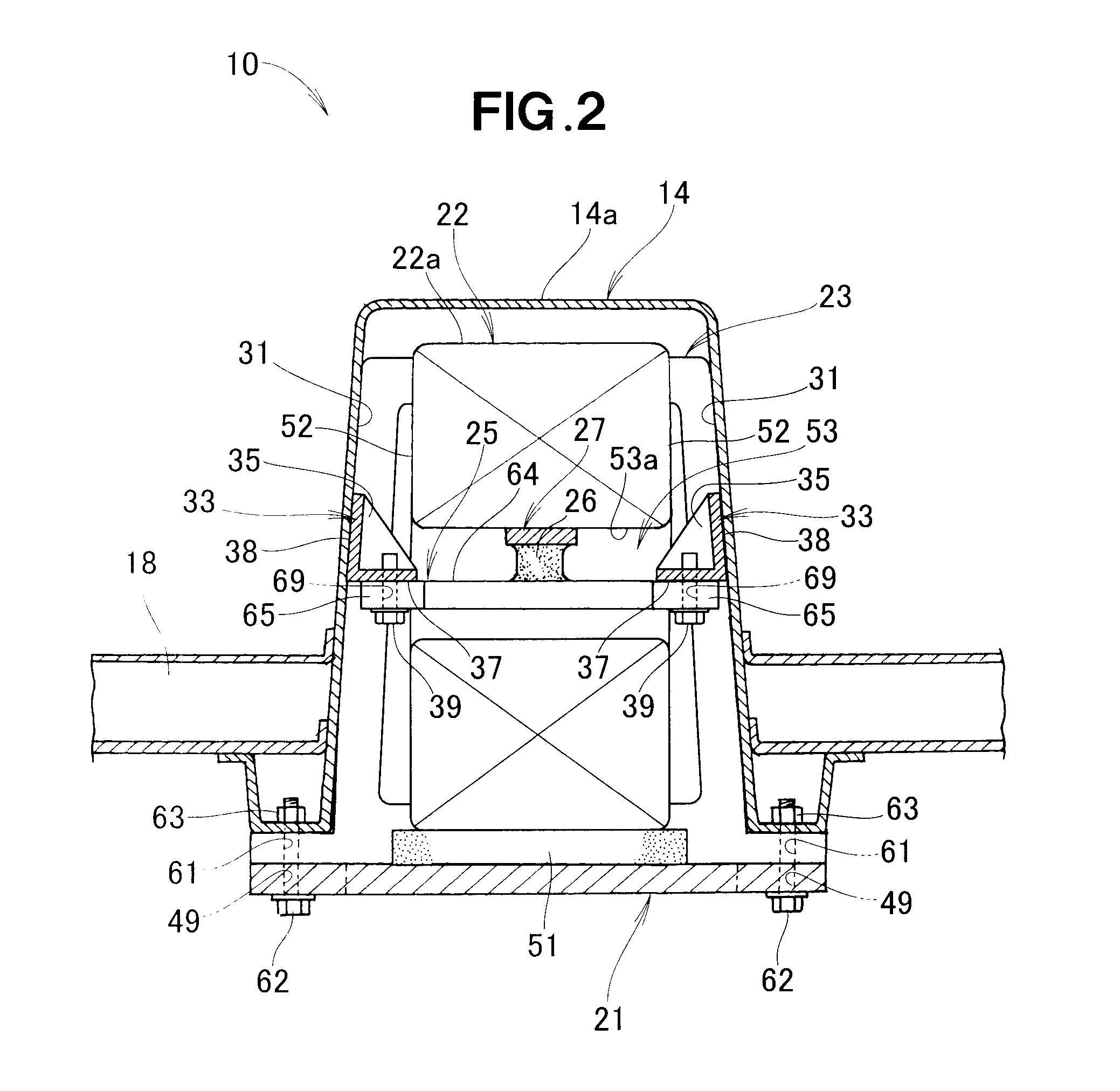
[0030]FIG. 1 is an exploded perspective view of an embodiment of a vehicle body floor structure of the present invention, and FIG. 2 is a sectional front view of the vehicle body floor structure shown in FIG. 1. The vehicle body floor structure shown in FIGS. 1 and 2 includes: a floor panel 13 defining a bottom section of a passenger compartment; a floor tunnel 14 provided on a laterally central portion of the floor panel 13 and extending in a front-rear direction of the vehicle body; a sub chassis 21 fixed to the floor tunnel 14; a stored component 22 mounted on the sub chassis 21; front and rear retaining members 23 that retain front and rear end portions of the stored component 22; a cross member 25 fixed to the floor tunnel 14; and a stay member 27 mounted on the cross member 25 via a resilient member 26 for supporting the stored component 22. Namely, the stay member 27 is supported, via the resilient member 26, in a substantially floating manner within the floor tunnel 14; thus...


PUM


Abstract

Vehicle body floor structure has a floor tunnel provided on a laterally central portion of a vehicle body floor panel and extending in a front-rear direction of a vehicle body, a desired stored component being stored in the floor tunnel. The stored component has a passageway formed therein to extend in a width direction of the vehicle body. The floor structure also has a cross member passed through the passageway of the stored component, the stored component is supported on the cross member via a resilient member, and the cross member is fixedly fastened at its opposite ends to the inner surfaces of opposed side walls of the floor tunnel.

Description

FIELD OF THE INVENTION[0001]The present invention relates to vehicle body floor structures having a floor tunnel that accommodates or stores a functional component, such as a fuel tank or a fuel cell stack.BACKGROUND OF THE INVENTION[0002]Heretofore, various anti-collision measures or techniques have been proposed for body floor structures of vehicles, particularly automotive vehicles. For example, vehicles are known in which a cross member is additionally provided in a floor tunnel in order to minimize or suppress deformation of the vehicle at the time of a lateral or side collision. Also known is a vehicle body floor structure constructed to disperse a load, produced by a lateral collision, across the entire vehicle using a seat structure. Examples of such a vehicle body floor structure are disclosed in Japanese Patent Application Laid-Open Publication No. 1109-136575 (hereinafter referred to as “patent literature 1”) and Japanese Patent Application Laid-Open Publication No. 2005-...

Claims


Application Information

Patent Timeline
Patent Type & Authority Applications(United States)
IPC IPC(8): B62D25/20
CPCB60K1/04B60K15/063B62D25/2036B62D25/025B62D25/20B60N2/4235
Inventor SUZUKI, HIROYOSHIOKUZAKI, SAYAKA
Owner HONDA MOTOR CO LTD
Why Eureka
Try Eureka