Power converting apparatus

a technology of power conversion apparatus and converter, which is applied in the direction of power conversion systems, ac-ac conversion, electrical apparatus, etc., can solve the problems of distortion of input current waveform, conversion is caused to perform commutation without generating loss, etc., to simplify the circuit for pulse wave modulation, suppress input current distortion, and suppress input current distortion

Active Publication Date: 2010-08-26
DAIKIN IND LTD
View PDF10 Cites 23 Cited by
  • Summary
  • Abstract
  • Description
  • Claims
  • Application Information

AI Technical Summary

Benefits of technology

[0017]According to the first aspect of the power converting apparatus of the present invention, before and after the timing at which the converter side is subjected to commutation, the period in which the zero voltage vector is generated equally acts on the current before commutation and the current after commutation. Accordingly, it is possible to suppress distortion of the input current using a single carrier.
[0018]According to the second or third aspect of the power converting apparatus of the present invention, the input current is capable of having a sine wave.
[0019]According to the fourth aspect of the power converting apparatus of the present invention, before and after the timing at which the virtual converter side is subjected to commutation, the period in which the zero voltage vector is generated equally acts on the current before commutation and the current after commutation. Accordingly, it is possible to suppress distortion of the input current using a single carrier.
[0020]According to the fifth or sixth aspect of the power converting apparatus of the present invention, the input current is capable of having a sine wave.
[0021]According to the seventh aspect of the power converting apparatus of the present invention, a triangular-wave-shape signal suitable for PWM modulation is used for a carrier signal, which simplifies a circuit for pulse wave modulation.
[0022]According to the eighth aspect of the power converting apparatus of the present invention, a sawtooth-wave-shape signal is used for a carrier signal, which simplifies carrier generation and modulation processing. These and other objects, features, aspects and advantages of the present invention will become more apparent from the following detailed description of the present invention when taken in conjunction with the accompanying drawings.

Problems solved by technology

Accordingly, in this period, input current of the converter does not flow as well, with the result that the converter is caused to perform commutation without generating loss resulting from switching.
As a result, in a case where a single triangular wave carrier is merely used in commutation of the converter as well as switching of the inverter, in some cases, the zero vector on the inverter side affects the periods before and after the commutation of the converter in an asymmetrical manner, leading to distortion of an input current waveform.

Method used


Image

  • Power converting apparatus
  • Power converting apparatus
  • Power converting apparatus

Examples


first embodiment

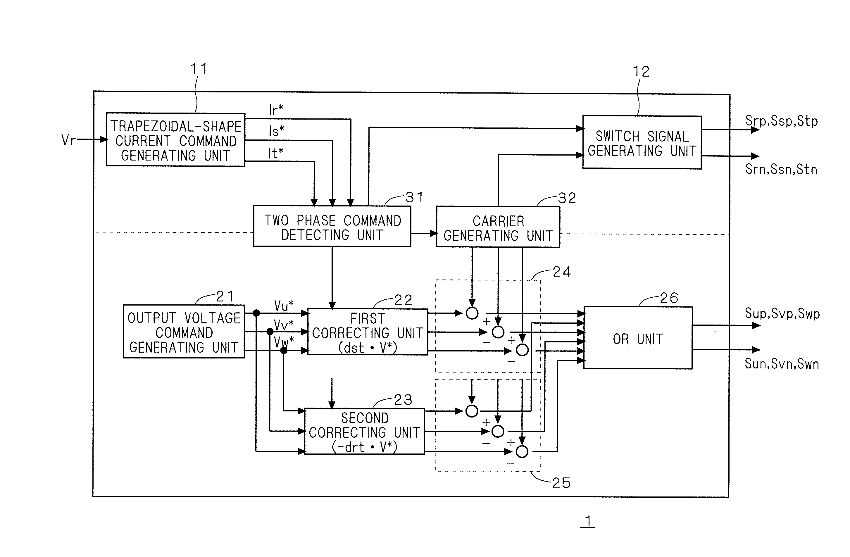
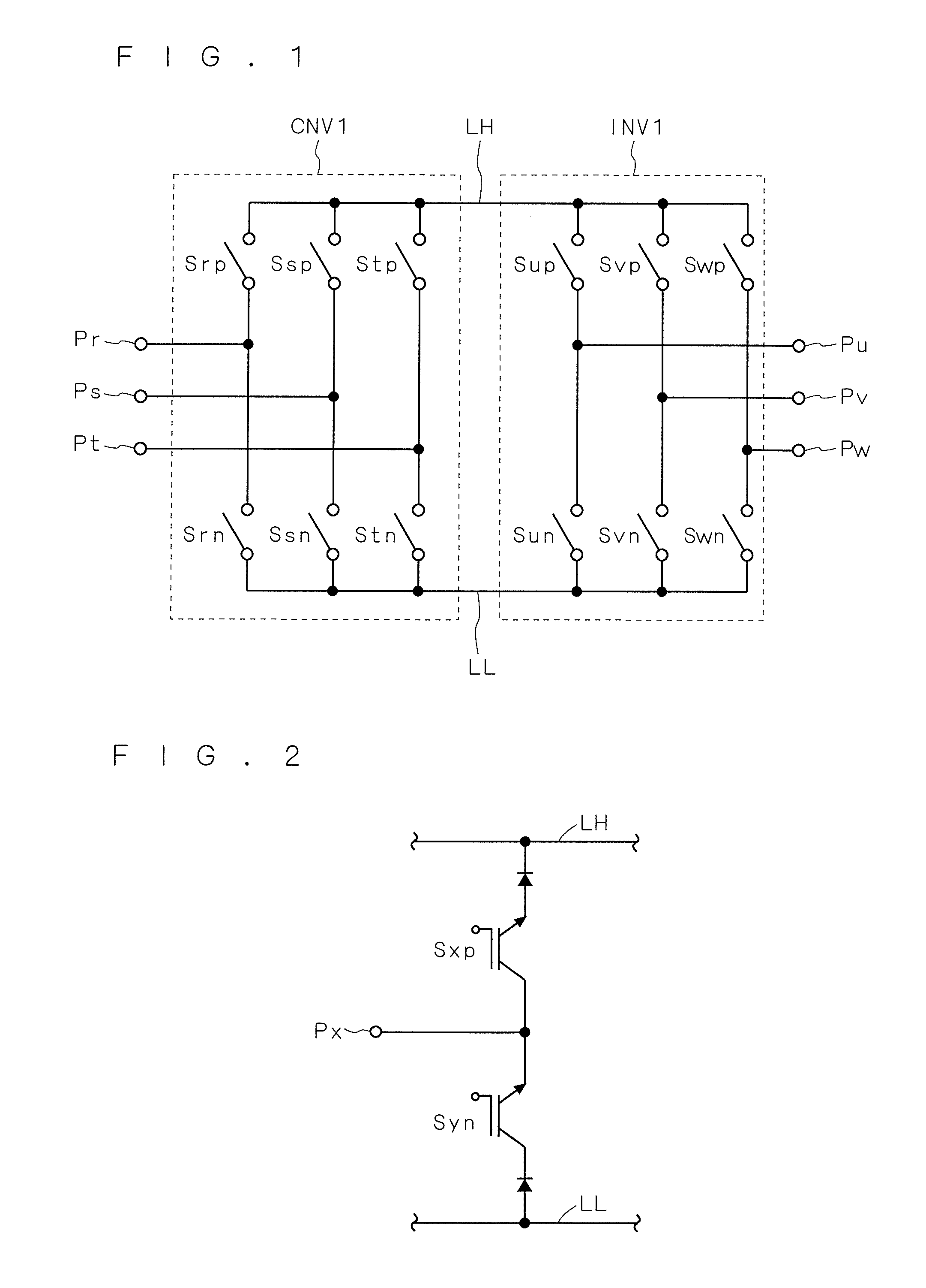
[0038]FIGS. 1 to 4 are configuration diagrams showing a conceptual example of a power converting apparatus according to a first embodiment. First, with reference to FIG. 1, the power converting apparatus includes three input terminals Pr, Ps and Pt, three output terminals Pu, Pv and Pw, DC power supply lines LH and LL, a converter CNV1, and an inverter INV1. Note that this power converting apparatus is a power converting apparatus which does not include power storing means such as a capacitor in the DC power supply lines LH and LL.

[0039]Phase voltages Vr, Vs and Vt of three-phase AC are input to the input terminals Pr, Ps and Pt, respectively. More specifically, for example, a three-phase AC power supply is connected to the input terminals Pr, Ps and Pt.

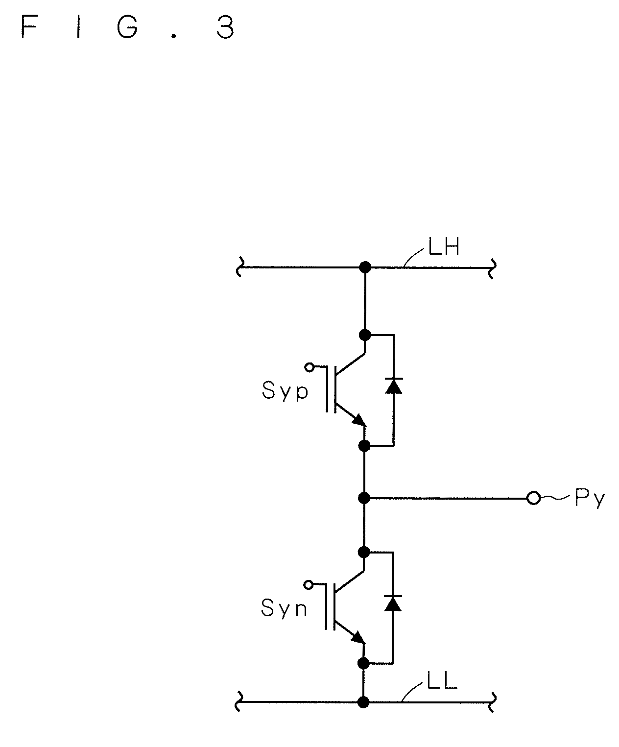
[0040]The converter CNV1 includes switch devices Srp, Ssp, Stp, Srn, Ssn and Stn. Three switch devices Srp, Ssp and Stp are connected between the DC power supply line LH and each of the input terminals Pr, Ps and Pt. Three switch dev...

first modification

[0103]Although a triangular-wave-shape carrier is used in the first embodiment, the carrier generating unit 32 generates a sawtooth-wave-shape carrier in the first modification. FIG. 15 shows a relationship among the carrier generated by the carrier generating unit 32, the input currents ir, is and it flowing through the r-phase, s-phase and t-phase, respectively, the current idc flowing through the DC power supply lines LH and LL, and switch signals supplied to the inverter INV1. FIG. 15 shows a carrier of approximately one cycle within a range of 30 degrees to 90 degrees in FIG. 5.

[0104]The carrier generating unit 32 generates a carrier having a sawtooth-wave-shape waveform, based on a position at which an amplitude (in this case, normalized to 1) of the waveform is internally divided into the current conduction rates drt and dst. Note that a sum of the current conduction rate drt and the current conduction dst is one, and thus the carrier based on the minimum value may be offset ...

second modification

[0110]The common carrier is used in the converter CNV1 and the inverter INV1 in the first embodiment and the first modification, which is not necessarily limited thereto.

[0111]FIG. 16 shows a relationship among the carrier generated by the carrier generating unit 32, the input currents ir, is and it flowing through the r-phase, s-phase and t-phase, respectively, the current idc flowing through the DC power supply lines LH and LL, and switch signals supplied to the inverter INV1.

[0112]The carrier generating unit 32 generates a first carrier having a waveform in which a slope is constant to time, based on a minimum value of a waveform value and generates a second carrier, based on a position at which an amplitude of the waveform is internally divided into the current conduction rates. Note that the generated first carrier may be offset to generate the second carrier.

[0113]The switch signal generating unit 12 outputs a switch signal on the converter side through comparison between the ...


PUM


Abstract

A power converting apparatus generates a carrier having a waveform in which an absolute value of a slope is constant with respect to time, based on a value for internally dividing amplitude of the waveform into first and second values. Commutation of a converter is performed when the carrier takes a reference. Adoption is allowed of a zero voltage vector as a switching mode of an inverter in a period in which the carrier takes a first command value to a second command value. A value for internally dividing a value from the reference to a maximum value of the carrier at a ratio between a third value and a fourth value is the first command value. A value for internally dividing a value from a minimum value of the carrier to the reference at a ratio between the third value and the fourth value is the second command value.

Description

CROSS-REFERENCE TO RELATED APPLICATIONS[0001]This U.S. National stage application claims priority under 35 U.S.C. §119(a) to Japanese Patent Application No. 2007-276792, filed in Japan on Oct. 24, 2007, the entire contents of which are hereby incorporated herein by reference.TECHNICAL FIELD[0002]The present invention relates to a power converting apparatus, and for example, to a direct power converting apparatus which is not provided with power storing means in a DC link unit thereof.BACKGROUND ART[0003]There is the technology of performing, in a power converting apparatus which is not provided with power storing means in a DC link unit between a converter and an inverter thereof, commutation of the converter side in a zero voltage vector period on the inverter side. That is, in the period when the inverter outputs zero voltage by a zero voltage vector, an output of the inverter is brought into a state of being short-circuited with only any one of a high potential side and a low pot...

Claims


Application Information

Patent Timeline
Patent Type & Authority Applications(United States)
IPC IPC(8): H02J1/00
CPCH02M5/4585H02M5/297
Inventor SAKAKIBARA, KENICHI
Owner DAIKIN IND LTD
Why Eureka
Try Eureka