
Systems and Methods for Driving High Power Stages Using Lower Voltage Processes

a technology of process and high power stage, applied in the field of levelshifter, can solve the problems of reducing the performance of the circuit, reducing the power consumption of the circuit, and reducing the effect of total harmonic distortion (thd), and achieve the effect of fast transition, power consumption and size advantages

Inactive Publication Date: 2010-08-26
SYNAPTICS INC
View PDF11 Cites 6 Cited by
  • Summary
  • Abstract
  • Description
  • Claims
  • Application Information

AI Technical Summary

Benefits of technology

The patent text describes a level shifter that is used in power drivers and class-D amplifiers to ensure that the voltage supplied to the output switches does not exceed the allowed limits. The level shifter provides a fast transition and maintains the target swing voltage even with changes in process, supply voltage, and temperature. The level shifter includes a pull-up transistor, a pull-down transistor, and a floating battery element. The patent also describes a method for maintaining a voltage between the high-side and low-side outputs. The technical effects of the patent text are improved power consumption and size of powered audio devices due to the use of class-D amplifiers, and the level shifter ensures optimal voltage swing and fast transitions with changes in control signals.

Problems solved by technology

The difficulty arises when the output requirements call for a higher voltage than is typically tolerated by the technology.
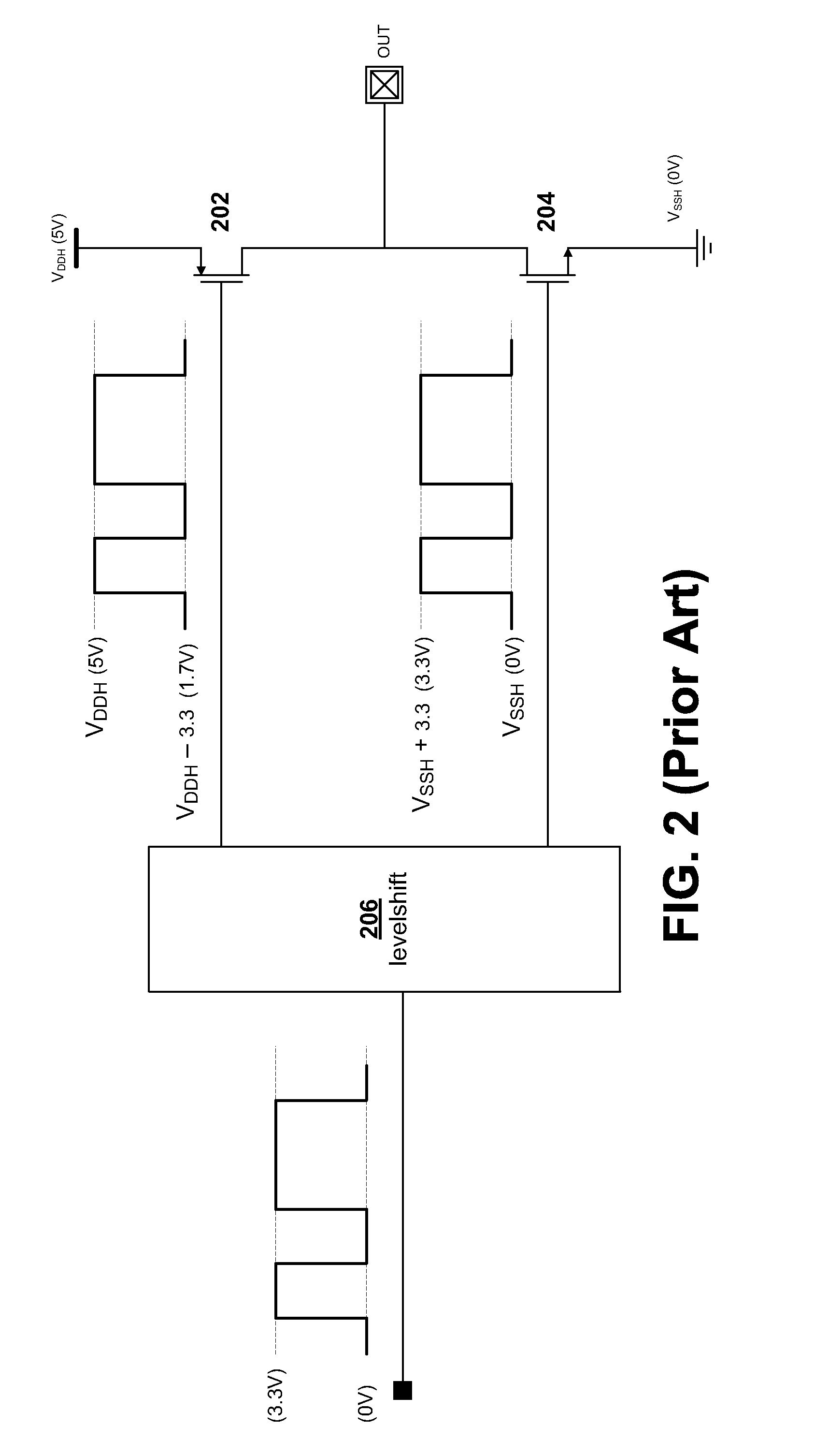
However, most advanced integration technologies use 0.35 μm or smaller geometries that only produce 3.3V tolerant FET devices.
Any delays between the signals can reduce the performance of the circuit; in class-D amplifiers a delay between the two signals in the output stage causes longer transition periods between the OFF and ON states of the output which produces a degradation in total harmonic distortion (THD).
In particular, variations in supply voltages VDDH and VSSH can be induced by large amounts of current flowing from and into the load which can be problematic.
In the case of a class-D amplifier the current can flow in either direction resulting in a significant increase or decrease of supply potentials.
The increased resistance can result in requiring a larger FET, an increase in power consumption, a decrease in performance or a combination of all three.
If the VSSH potential decreases the low-side switch 204 switch VGS is increased and may exceed the technology limitations causing reliability issues.
This is especially challenging in the case of battery-operated systems where the positive power rail voltage can vary substantially depending on battery conditions.
The bootstrap capacitor must be large compared to the capacitive load given by the high-side FET device, therefore it cannot be integrated.
This is undesirable because to include this solution as part of an integrated package, additional pins must be supplied in order to use an external capacitor.
The suboptimal voltage swing as mentioned above leads to higher power consumption and lower performance by the output stage or requires a larger high-side switch.

Method used


Image

  • Systems and Methods for Driving High Power Stages Using Lower Voltage Processes
  • Systems and Methods for Driving High Power Stages Using Lower Voltage Processes
  • Systems and Methods for Driving High Power Stages Using Lower Voltage Processes

Examples


Embodiment Construction

[0027]A detailed description of embodiments of the present invention is presented below. While the disclosure will be described in connection with these drawings, there is no intent to limit it to the embodiment or embodiments disclosed herein. On the contrary, the intent is to cover all alternatives, modifications and equivalents included within the spirit and scope of the disclosure as defined by the appended claims.

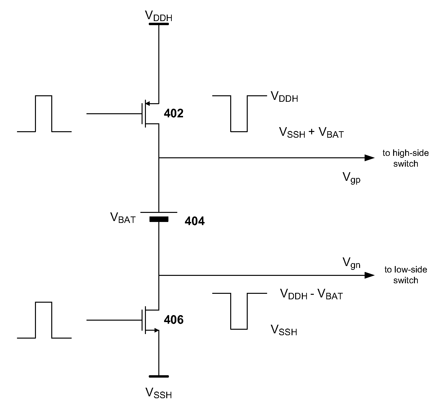
[0028]FIG. 4 is a circuit diagram of an embodiment of a level-shifter. The level shifter comprises pull-up PFET 402, pull-down NFET 406 and floating battery element 404. PFET 402 when switched ON pulls Vgp up to the voltage supplied by the high supply rail which has a high supply voltage denoted by VDDH. NFET 406 when switched ON pulls Vgn down to the voltage supplied by the low supply rail which has a low supply voltage denoted by VSSH and is sometimes set to the ground potential. Floating battery element 404 maintains its voltage VBAT across its two terminals regardl...


PUM


Abstract

In today's environment class-D amplifiers are used to provide an integrated solution for applications such as powered audio devices due to their advantages in power consumption and size over more traditional analog amplifiers. Due to power output requirements, the output stages of power drivers such as class-D amplifiers require a supply voltage in excess of the technologically allowed voltage for the switches in the output stage. A level shifter is used to ensure voltages supplied to the output switches do not exceed the technological limits. An ideal level shifter should provide the optimal voltage swing to output switches under all process, supply voltage and temperature (PVT) variations. The ideal level shifter should also provide fast transitions when the control signal changes from high to low and low to high.

Description

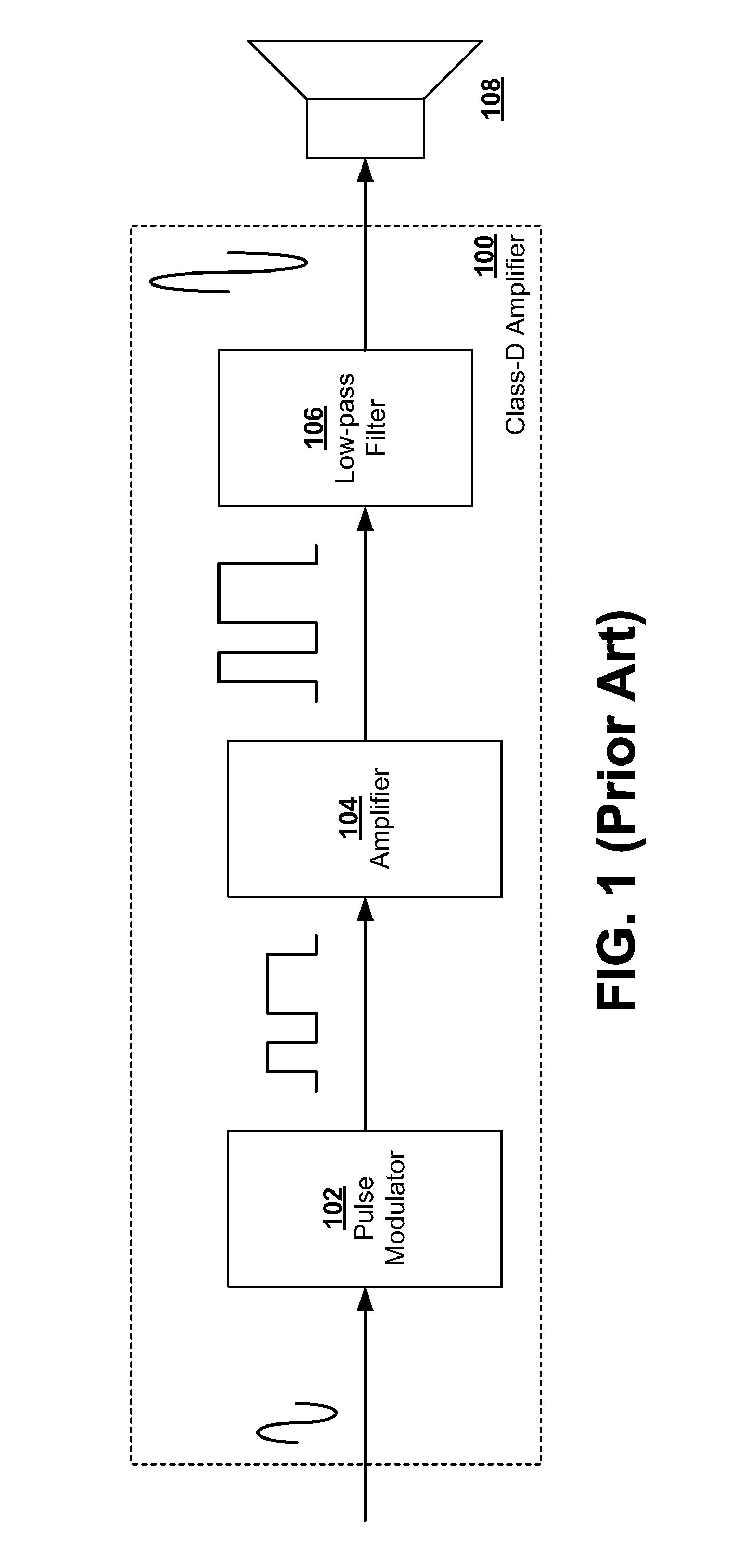
BACKGROUND OF THE INVENTION[0001]1. Field of the Inventions[0002]The invention relates to integrated power driver circuits and in particular to an improved level-shifter for driving the output stage of an integrated power driver.[0003]2. Background Information[0004]In today's environment, class-D amplifiers are used to provide an integrated solution for applications such as powering audio devices. Class-D amplifiers have an advantage in power consumption and size over more traditional analog amplifiers. Generally, they do not require bulky transformers or heat sinks making them more suitable for integrated circuits.[0005]In particular, the class-D amplifier unlike a traditional amplifier produces an output comprising a sequence of pulses. Typically, these pulses vary in width or in density in methods known as pulse width modulation (PWM) or pulse density modulation (PDM). The average value of these pulses represents the instantaneous amplitude of the output signal. These pulses intr...

Claims


Application Information

Patent Timeline
Patent Type & Authority Applications(United States)
IPC IPC(8): H03K19/0175
CPCH03K17/102
Inventor CRESPI, LORENZOPATEL, KETAN B.
Owner SYNAPTICS INC
Learn More