Transistor overcurrent detection circuit with improved response time

a detection circuit and overcurrent technology, applied in the direction of electrical equipment, electronic switching, pulse technique, etc., can solve the problems of increasing current that builds, reducing the detection efficiency of overcurrent detection, and reducing so as to reduce the overall overcurrent detection size, the effect of doubling the functionality

Active Publication Date: 2009-12-01
TEXAS INSTR INC
View PDF4 Cites 2 Cited by
  • Summary
  • Abstract
  • Description
  • Claims
  • Application Information

AI Technical Summary

Benefits of technology

[0017]According to an advantage of the present invention, the overcurrent detection holes and creeping overcurrent reference values can be avoided or eliminated. Portions of positive Vds measurement circuitry can be reused for negative Vds sensing, to permit a relative reduction in overall overcurrent detection size while doubling the functionality. Positive and negative Vds sensing may be obtained with p-type or n-type semiconductor devices, with an advantage in size for p-type devices.
, the overcurrent detection holes and creeping overcurrent reference values can be avoided or eliminated. Portions of positive Vds measurement circuitry can be reused for negative Vds sensing, to permit a relative reduction in overall overcurrent detection size while doubling the functionality. Positive and negative Vds sensing may be obtained with p-type or n-type semiconductor devices, with an advantage in size for p-type devices.

Problems solved by technology

A particular issue that occurs with class D power amplifiers is increasing current that builds with each switching cycle of the amplifier output stage under certain conditions.
In a number of class D power amplifiers, overcurrent detection in the above situation is difficult because conventional overcurrent detectors have a cyclic speed in the range of 100-150 ns.
Due to the closed loop delay in detecting overcurrent, potentially damaging situations may arise that are not detected by the overcurrent detector until too late.
This type of detection and control, drawn from worst case models in high temperature conditions, becomes very challenging in noisy environments.
In particular, current detection of a high side switch and a switching half bridge in a noisy environment with approximately 40V PVDD with reverse recovery events on the order of 10 amps and lasting 20-30 ns becomes very challenging.
In addition, the coordination of the overcurrent detection and gate drive control can be somewhat complicated and add cost to the circuitry.
Because FETs in these applications often experience negative voltages across their outputs, the overcurrent detector described above only detects current conditions in half of the possible number of voltage measurement situations.
These types of overcurrent detectors do not obtain any information or have any knowledge of other states of the FETs, such as when the FET output voltage is negative.
In a half bridge switching design, the lack of knowledge about two out of the four possible states for the output voltages of the two transistors provides a challenge in these types of overcurrent detectors to be designed with a very fast closed loop response, which can be complicated and expensive in practice.
Some of these drawbacks are notable in class D audio amplifiers, and include such overcurrent issues as overcurrent detection holes and creeping current values.
These drawbacks are particularly noticeable in cycle by cycle control in high voltage applications.
The results of these overcurrent detection drawbacks are collapsing power supplies and the use of more expensive, bulkier and higher saturation current value inductors.
Part of the difficulty in eliminating the creeping overcurrent value illustrated in the graph of FIG. 2 is that the closed loop cycle time for the overcurrent detector should be below approximately 50 ns, which is a difficult specification to obtain.

Method used


Image

  • Transistor overcurrent detection circuit with improved response time
  • Transistor overcurrent detection circuit with improved response time
  • Transistor overcurrent detection circuit with improved response time

Examples


Embodiment Construction

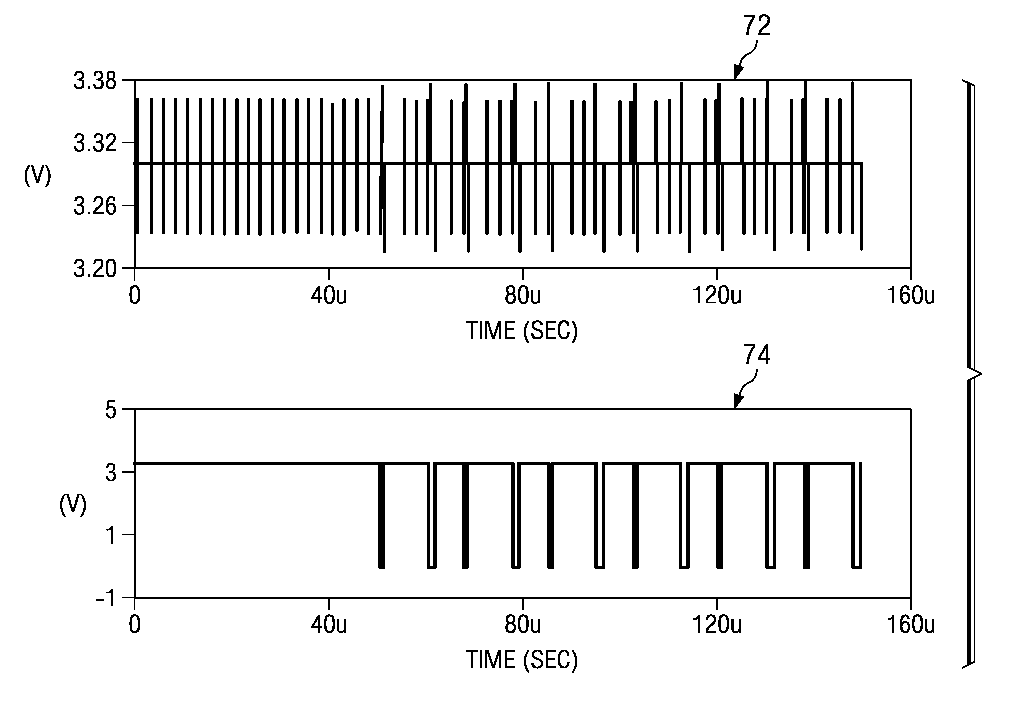
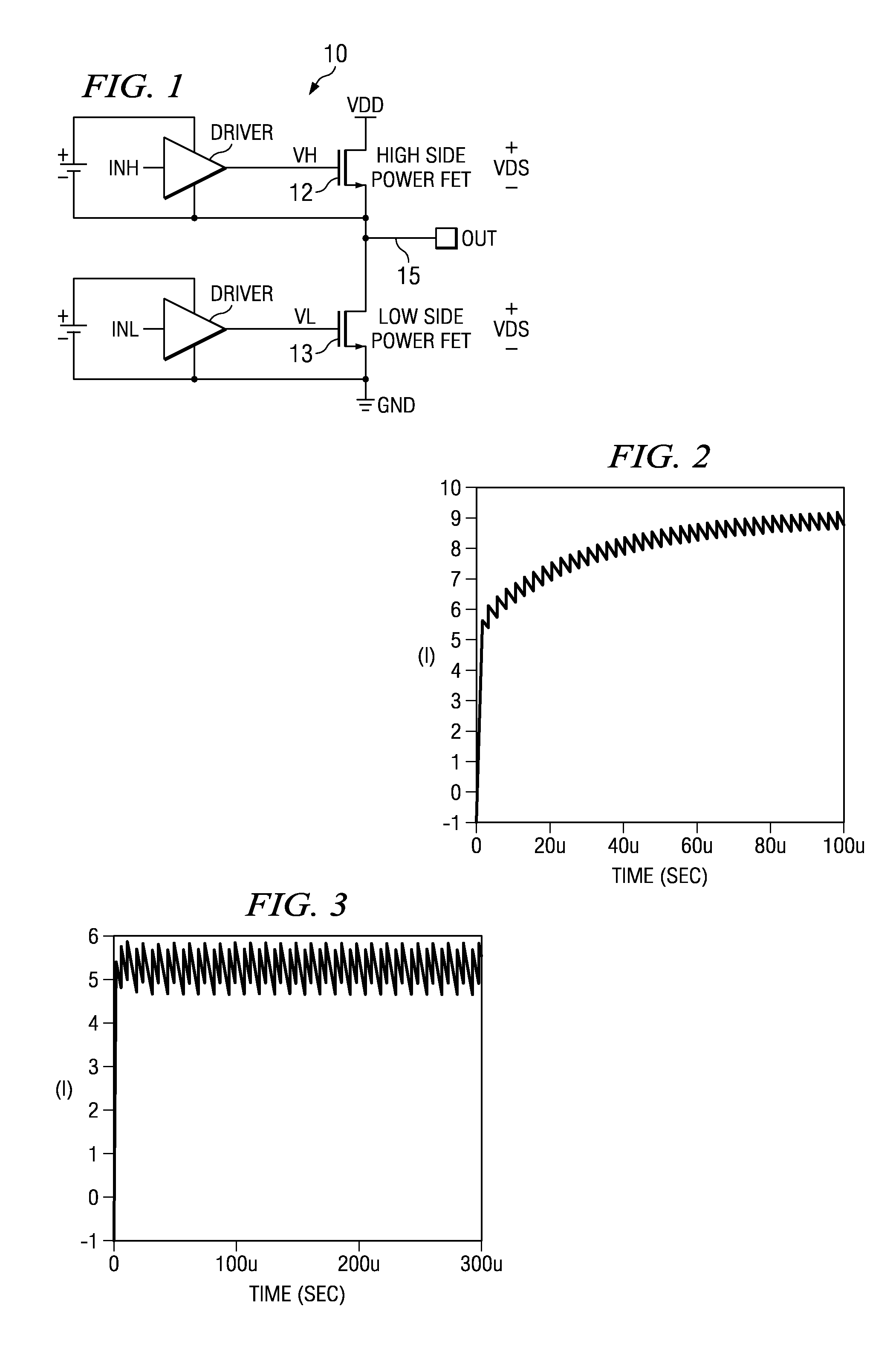
[0035]Referring now to FIG. 1, a circuit diagram of a switching half bridge is illustrated as circuit 10. Circuit 10 includes a high side FET 12 and a low side FET 13, that provide a switched output at a common node 15. Node 15 is typically connected to a load that can be inductive. When FETs 12 and 13 are switched using a PWM control arrangement, the voltages across the drains and sources of FETs 12 and 13 can be positive or negative, related to current flow in FETS 12, 13. When the voltage is positive, as indicated by the polarity on the outputs of FETs 12 and 13, voltage Vds for FETs 12 and 13 is positive and current flows in a positive direction from (+) to (−). An overcurrent detector can be connected to FETs 12 and 13 to determine current through the FETs based on the positive voltage Vds. Conventionally, an overcurrent sensor would detect the positive voltage Vds to measure the current through the corresponding FET. Accordingly, such an overcurrent detector would work when th...


PUM


Abstract

A circuit and method for determining overcurrent in a FET detects an output voltage of the FET in both a positive and negative polarity. The related positive or negative currents through the FET can be measured to determine whether an overcurrent condition exists. By measuring positive and negative currents in the FET, the overcurrent detector can obtain twice as much information as when measuring a positive current alone, and can respond more readily to overcurrent conditions. The overcurrent detector avoids the constraints typically observed in cycle-by-cycle PWM control with single polarity Vds sensing, while permitting a relaxation in the timing requirements for current sensing. A spike suppression circuit also contributes to longer sensing intervals.

Description

BACKGROUND OF THE INVENTION[0001]Current detection in power FETS has long been used in a number of applications for a variety of purposes. For example, current detection may be used to help control the power FET or other components of a system in which the power FET resides. In most power switching applications, overcurrent detection can help identify potentially dangerous situations where a power FET may be conducting more than a rated current. Accordingly, overcurrent detection is highly desirable in power applications in which power FETs are used.[0002]A particular power switching application where overcurrent detection is particularly useful is in class D power amplifiers. A particular issue that occurs with class D power amplifiers is increasing current that builds with each switching cycle of the amplifier output stage under certain conditions. In a number of class D power amplifiers, overcurrent detection in the above situation is difficult because conventional overcurrent de...

Claims


Application Information

Patent Timeline
Patent Type & Authority Patents(United States)
IPC IPC(8): H02H3/08H02H9/02H02H3/00
CPCH03K17/082
Inventor KAYA, CETINTENG, JAMESNEESGAARD, CLAUS
Owner TEXAS INSTR INC
Why Eureka
Try Eureka