MEMS capacitive device and method of forming same

a capacitive device and microelectromechanical technology, applied in the direction of mechanically variable capacitors, capacitors with electrode distance variation, variable capacitors, etc., can solve the problems of affecting the yield and capacitor accuracy of a single substrate device, exacerbated difficulty, and high temperature annealing of piezoelectric materials

Inactive Publication Date: 2010-08-26
NORTH STAR INNOVATIONS
View PDF1 Cites 21 Cited by
  • Summary
  • Abstract
  • Description
  • Claims
  • Application Information

AI Technical Summary

Problems solved by technology

One difficulty in designing and fabricating a MEMS parallel plate capacitor, such as capacitive device 20, is to achieve acceptable process tolerance while concurrently achieving successful device reproducibility in mass production.
This difficulty is exacerbated when using piezoelectric actuation in the MEMS capacitor.
However, fabrication processes for piezoelectric material requires high temperature annealing (e.g., six hundred to seven hundred degrees Celsius).
The high temperature processing can result in stress and thermal mismatch effects that adversely affect capacitor yield and capacitor accuracy in a single substrate device, such as MEMS capacitive device 20.
Unfortunately, the roughness of contact surface 84 leads to poor reproducibility.

Method used


Image

  • MEMS capacitive device and method of forming same
  • MEMS capacitive device and method of forming same
  • MEMS capacitive device and method of forming same

Examples


Embodiment Construction

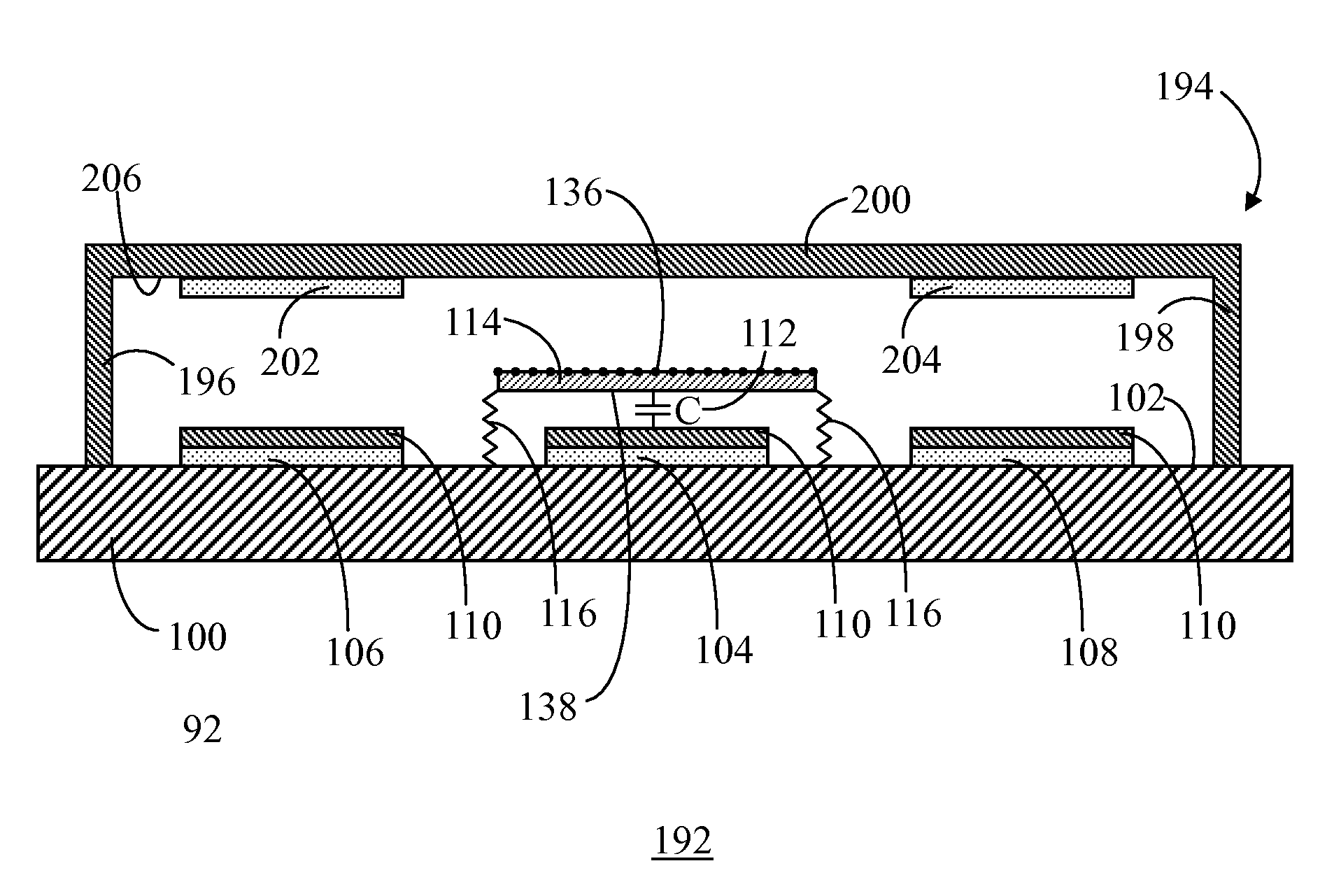
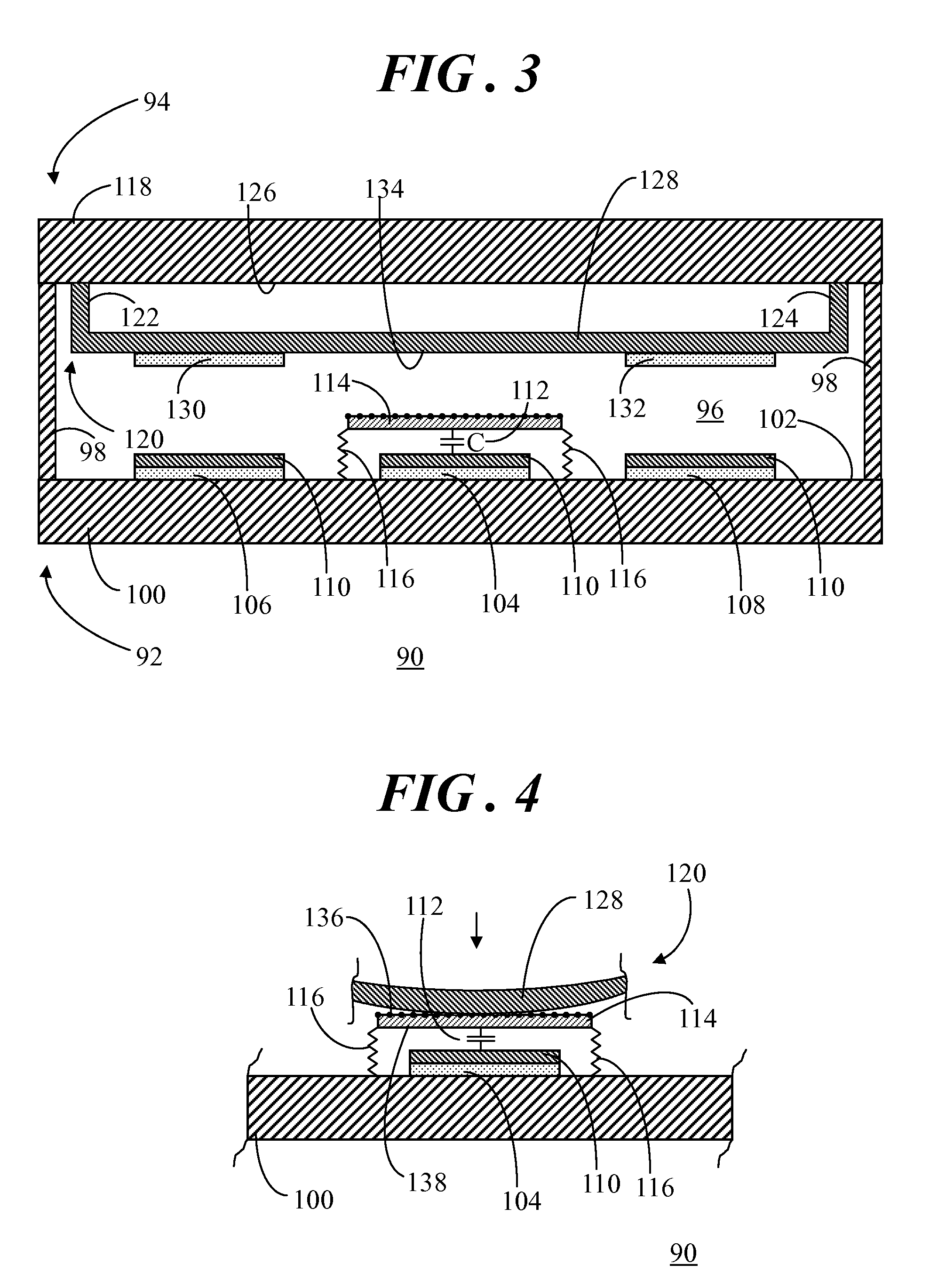
[0031]An embodiment entails a microelectromechanical systems (MEMS) capacitive device having separate actuators and capacitor plates. Another embodiment entails a method of fabricating the MEMS capacitive device using surface micromachining and substrate bonding processes. The MEMS capacitive device includes piezoelectric actuators formed on a movable element that is physically separate from fixed and movable capacitor plates of a parallel plate capacitor. The term “physically separate” refers to a configuration in which the movable element and actuators on the movable element form a separate structure that is not in physical contact with the fixed and movable capacitor plates unless the MEMS capacitive device is actuated. Actuation of the MEMS capacitive device causes abutment of the movable element against the movable capacitor plate, which moves the movable capacitor plate toward the fixed capacitor plate to alter a capacitance between the movable and fixed capacitor plates. The ...


PUM

PropertyMeasurementUnit
temperatureaaaaaaaaaa
capacitanceaaaaaaaaaa
forceaaaaaaaaaa

Abstract

A MEMS capacitive device (90) includes a fixed capacitor plate (104) formed on a surface (102) of a substrate (100). A movable capacitor plate (114) is suspended above the fixed capacitor plate (104) by compliant members (116) anchored to the surface (102). A movable element (120) is positioned in spaced apart relationship from the movable capacitor plate (104) and has an actuator (130) formed thereon. Actuation of the actuator (130) causes abutment of a portion of the movable element (120) against a contact surface (136) of the movable plate (114). The abutment moves the movable plate (114) toward the fixed plate (104) to alter a capacitance (112) between the plates (104, 114). Another substrate (118) may be coupled to the substrate (100) such that a surface (126) of the substrate (118) faces the surface (102) of the substrate (100). The movable element (120) may be formed on the surface (126).

Description

TECHNICAL FIELD OF THE INVENTION[0001]The present invention relates generally to microelectromechanical systems (MEMS) devices. More specifically, the present invention relates to a MEMS capacitive device with separate actuator and capacitor plates and method of forming same.BACKGROUND OF THE INVENTION[0002]Microelectromechanical systems (MEMS) variable capacitive devices are components implemented in a number of systems including, for example, reconfigurable radio-frequency (RF) systems. MEMS variable capacitive devices are tunable capacitors that enable either binary states of capacitance (e.g., C1 and C2) or continuously variable states of capacitance over a range of values. In a tunable parallel plate capacitor, change in capacitance is effected by varying the distance between the metal layers forming the capacitor plates via an actuation method, such as piezoelectric and / or electrostatic actuation. Upon actuation, the distance between the capacitor plates is tuned via one or mo...

Claims


Application Information

Patent Timeline
Patent Type & Authority Applications(United States)
IPC IPC(8): H01G5/16H01L21/20H01L21/02
CPCB81B3/0072B81B2201/0221H01G5/011Y10T29/435H01L28/40H01L41/0973H01G5/18H10N30/2047
Inventor LIU, LIANJUNMILLER, MELVY F.
Owner NORTH STAR INNOVATIONS
Why Eureka
Try Eureka