High efficiency light emitting diode apparatus

a light-emitting diode, high-efficiency technology, applied in the direction of lighting and heating apparatus, semiconductor devices for light sources, lighting support devices, etc., can solve the problems of reducing the brightness of leds or even burning out, affecting the operation of traditional devices, and still affecting the control of working temperature, so as to enhance the heat dissipation effect, high-efficiency light-emitting, and excellent heat dissipation effect of flow paths

Active Publication Date: 2010-08-26
TAIWAN GREEN POINT ENTERPRISE
View PDF1 Cites 37 Cited by
  • Summary
  • Abstract
  • Description
  • Claims
  • Application Information

AI Technical Summary

Benefits of technology

[0011]The objects of the present invention are to provide a high efficiency light emitting diode apparatus. In which, the heat dissipating effect of the flow paths is excellent. The structure forming two flow paths can enhance the heat dissipating effect. The auxiliary element can strengthen the overall illuminating effect. Plus, the auxiliary element can make the light more uniformly. Moreover, this invention can solve the problems about the brightness decreases, the overall heat dissipating effect is poor, and the illuminating effect is limited. Besides, it can find a best point that is well balanced among the amount of the LEDs, the brightness issue, and the heat dissipating effect.

Problems solved by technology

If it is overheated, the brightness of the LEDs decreases or even burns out.
Under such circumstance, how to control the working temperature becomes a major issue.
However, the traditional devices still have the following problems.
[a] The overall heat dissipating effect is poor.
Because the heat dissipation is poor, it causes the brightness gradually decreases or even dies out.
Therefore, the heat dissipating effect is poor.
Also, the product life is relatively shorter.
[2] The illuminating effect is limited.
Thus, the illuminating effect is limited.
However, it also generates other serious problems such as poor heat dissipation, big power consumption, etc.
So, it is hard to find a best point that is well balanced among the amount of the LEDs, the brightness issue, and the heat dissipating effect.

Method used


Image

  • High efficiency light emitting diode apparatus
  • High efficiency light emitting diode apparatus
  • High efficiency light emitting diode apparatus

Examples


Embodiment Construction

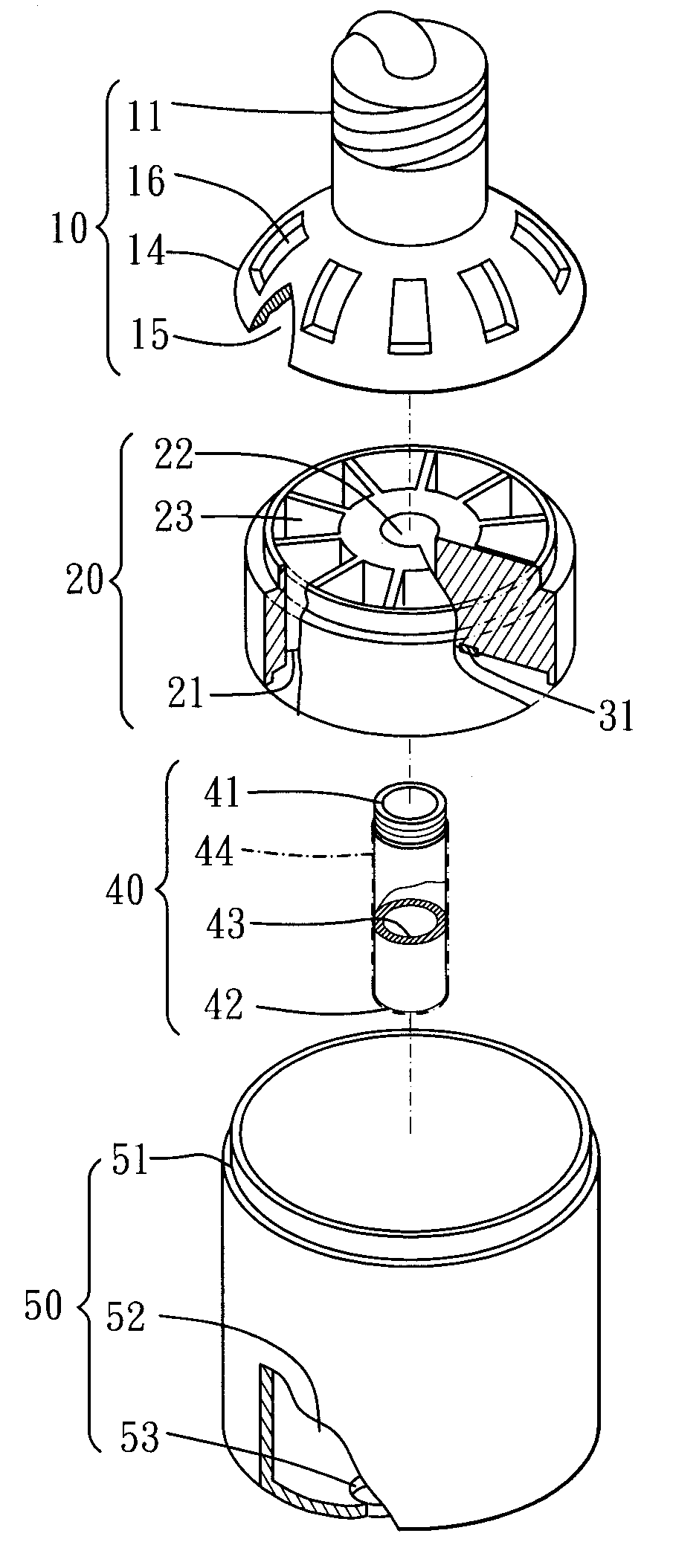
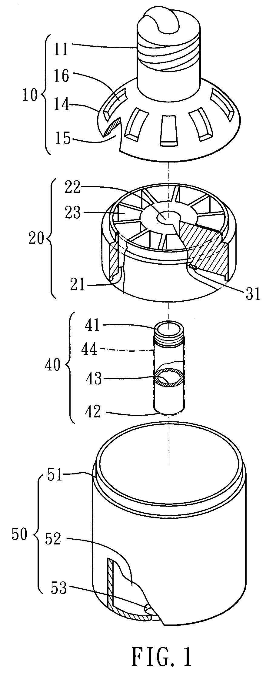
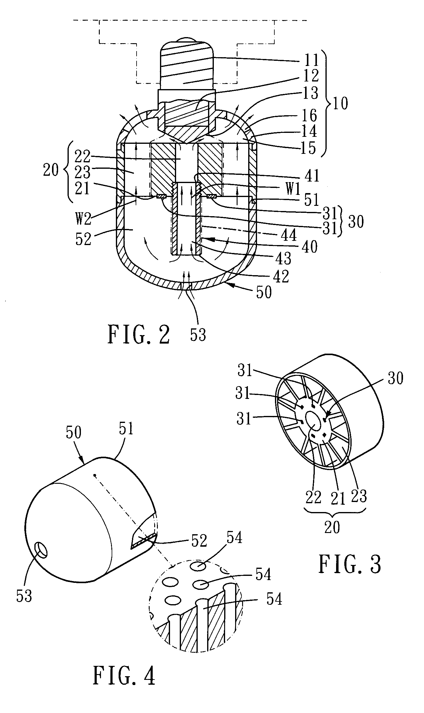
[0041]FIGS. 1 and 2 show the first preferred embodiment of the present invention. This invention is a high efficiency light emitting diode apparatus. It mainly comprises a connector 10, a heat dissipating body 20, a light generator 30, a central venting portion 40, and a transparent casing 50.

[0042]Concerning this connector 10, it has an electric connecting portion 11, an electrical processor 12, a flow guider 13 and a connecting housing 14. The electrical processor 12 is connected with the electric connector 11. The flow guider 13 is disposed at an end opposite to the electric processor 12. The connecting housing 14 is disposed on an outer edge of this electrical processor 12. Further, the connecting housing 14 has an inner side that forms an air guiding chamber 15. In addition, the connecting housing 14 has at least one vent 16.

[0043]The heat dissipating body 20 (as shown in FIG. 3) is disposed on one end of the connector 10. The heat dissipating body 20 has a working surface 21 (...


PUM


Abstract

The high efficiency light emitting diode apparatus mainly comprises a connector, a heat dissipating body, a light generator, a central venting portion, and a transparent casing. This connector has a flow guider, a flow chamber and a vent. The light generator contains several LEDs. The heat dissipating body includes an inner passage and an outer passage. The central venting portion has a central channel. An inner flow path and an outer flow path are formed. So, the heat dissipating effect of the flow paths is excellent. The structure forming two flow paths can enhance the heat dissipating effect. The auxiliary element can strengthen the overall illuminating effect. Plus, the auxiliary element can make the light more uniformly.

Description

BACKGROUND OF THE INVENTION[0001]1. Field of the Invention[0002]The present invention relates to a high efficiency light emitting diode apparatus. It includes an inner flow path and an outer flow path. The heat dissipating effect of the flow paths is excellent. The structure forming two flow paths can enhance the heat dissipating effect. The auxiliary element can strengthen the overall illuminating effect. Plus, the auxiliary element can make the light more uniformly.[0003]2. Description of the Prior Art[0004]Referring to FIG. 11, it shows a first traditional light emitting diode illuminating device. It contains many light emitting diodes (or briefly referred as LEDs) 81 disposed around so as to form an illuminating device 80.[0005]As shown in FIG. 12, it exhibits a second traditional light emitting diodes 91 disposed on a seat 92 that forms another illuminating device 90.[0006]When the LEDs are working, they remain at a working temperature. If it is overheated, the brightness of th...

Claims


Application Information

Patent Timeline
Patent Type & Authority Applications(United States)
IPC IPC(8): F21S4/00F21V29/00
CPCF21V3/02F21V29/004F21V29/02F21Y2101/02F21V29/83F21K9/52F21V29/506F21V29/673F21K9/135F21K9/232F21K9/61F21Y2115/10F21V29/70
Inventor CHIU, SHAO-CHENRENN, YIH-HUATSAI, RAY-LONGCHANG, SHIH-TSUNGCHENG, CHI-FENG
Owner TAIWAN GREEN POINT ENTERPRISE
Why Eureka
Try Eureka