Systems and methods for power connection

a technology of power connection and system, applied in the direction of coupling device connection, coupling device details, cooling/ventilation arrangement, etc., can solve the problems of low mechanical yield strength properties of materials with high electrical conductivity, unable to withstand many assembly and disassembly cycles without damage, and only providing limited line contact. , the effect of not much surface area

Inactive Publication Date: 2010-08-26
CLEAN WAVE TECH
View PDF20 Cites 12 Cited by
  • Summary
  • Abstract
  • Description
  • Claims
  • Application Information

AI Technical Summary

Benefits of technology

[0011]In accordance with one aspect of the invention, the power connection assembly may provide an efficient electrical and robust mechanical connection. The power connection assembly may include a power cable connector that may be configured to contact a power connection block. The power cable connector and power connection block may be formed of electrically conductive materials. The power cable connector and power connection block may contact one another over a relatively large surface area, and may be electrically and mechanically connected. The power connection block may include an insert formed of a relatively high strength material. A fastener may be mechanically connected to the insert of the power connection block, and may be used to apply pressure to form the connection between the power cable connector and power connection block. The fastener and insert may provide a robust mechanical connection, but need not be part of the electrical connection formed by the power cable connector and the power connection block.
[0013]The sealed power connection may also provide insulating and sealing configurations in accordance with another aspect of the invention. An insulator may electrically insulate the connection provided between the power cable connector and the power connection block from the housing of the electric machine. The design may also provide a sealed connection that may prevent cooling fluid used to cool the power connection block, or other fluids within the electric machine, from leaking out of the electric machine.

Problems solved by technology

One drawback for this stud connection design is that the threaded stud 10 and locking nut 13 need to be constructed of material with relatively high electrical conductivity, especially when used in high-current applications.
However, materials with high electrical conductivity tend to also have low mechanical yield strength properties, making them prone to failure when threaded hardware is used to secure the electrical connection, and thus will not survive many assembly and disassembly cycles without damage.
Additionally, another drawback of a traditional stud connection design is that the electrical current must flow through the threads of the locking nut 13 to the threads of the stud 10 to complete the electrical circuit, providing only limited line contact and not much surface area contact.
This is especially troublesome in high-current applications, where the limited electrical contact leads to additional resistive losses and overheating of the connection.
The entire connection needs to be accessible, yet also contained in some type of sealed enclosure, making this design approach undesirable where a compact form factor is important.

Method used


Image

  • Systems and methods for power connection
  • Systems and methods for power connection
  • Systems and methods for power connection

Examples


Embodiment Construction

[0028]While preferable embodiments of the invention have been shown and described herein, it will be obvious to those skilled in the art that such embodiments are provided by way of example only. Numerous variations, changes, and substitutions will now occur to those skilled in the art without departing from the invention. It should be understood that various alternatives to the embodiments of the invention described herein may be employed in practicing the invention.

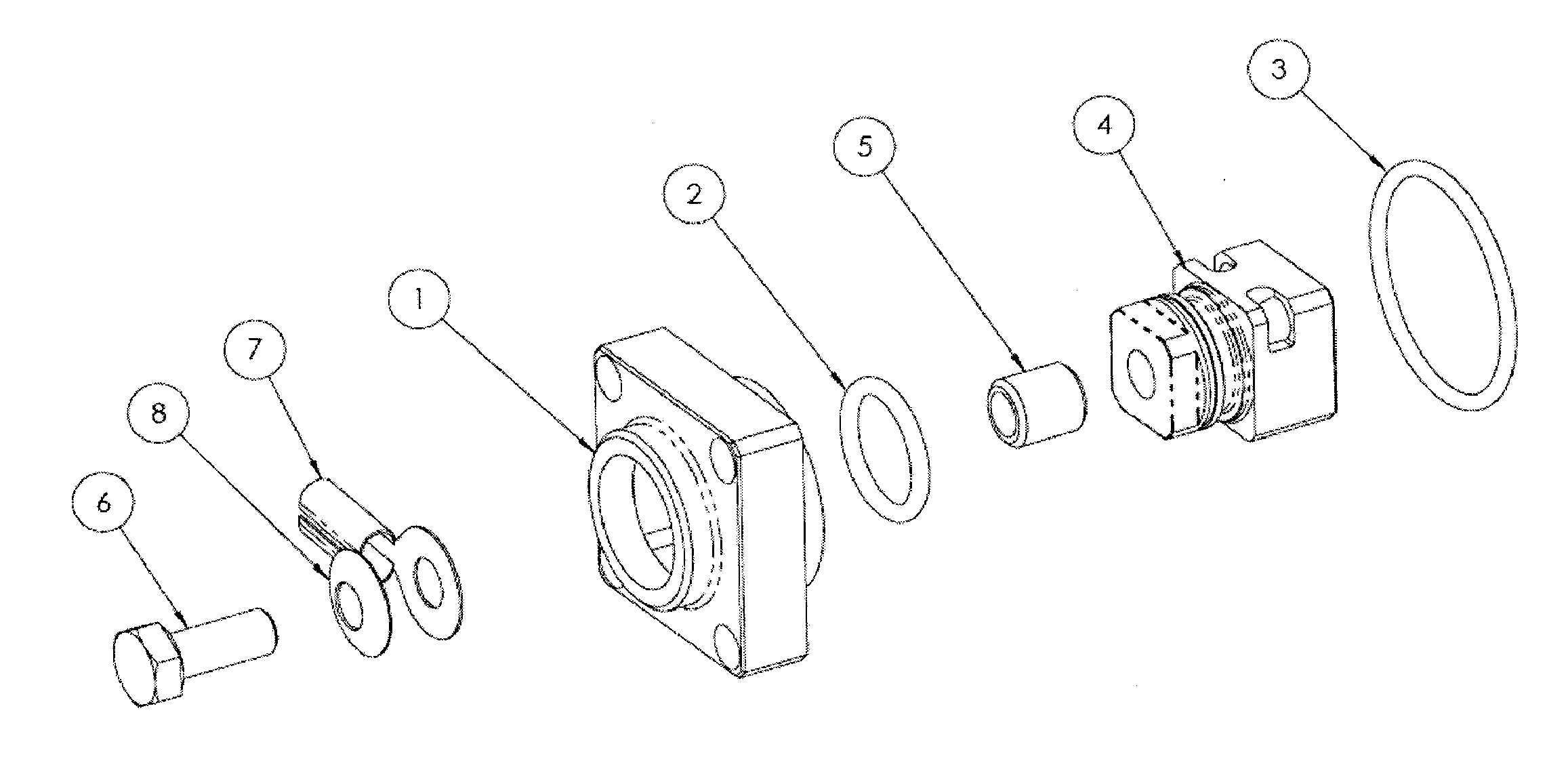
[0029]The invention provides systems and methods for power connection (also referred to herein as a sealed power connection, although some embodiments may not require the power connection be sealed). The power connection may be used in any application, including, but not limited to, electric machines. For example, power may be provided by a power source, which may or may not be external to the electric machine, and may be transferred through the power connection to the internal wirings or components of the electric mach...


PUM


Abstract

The invention provides systems and methods for power connection, which may be a sealed power connection. The sealed power connection may be used with electric machines, which may be fluid cooled. The sealed power connection may provide an effective electrical connection while providing a robust mechanical connection. The sealed power connection may provide electrical insulation of the connection from the machine housing, and may also be sealed to provide for internal fluid cooling of the electric machine and fluid cooling of the connection.

Description

CROSS-REFERENCE[0001]This application claims the priority of U.S. Provisional Application Ser. No. 61 / 154,316, dated Feb. 20, 2009 which is incorporated herein by reference.BACKGROUND OF THE INVENTION[0002]High power electric machines require robust power connections capable of reliably transferring high currents and insulating high voltages. In the case of internally fluid cooled machines, the connection also requires sealing against the machine enclosure to prevent leakage of cooling fluids.[0003]One traditional method used for making power connections to electric machines is to provide a threaded stud constructed of material with relatively high electrical conductivity, such as copper or brass, connected to the internal wiring of the machine. With this method, as illustrated in FIG. 1, the threaded stud 10 is inserted through an insulated block 11. The assembly is then inserted through the machine housing wall 17 and captured with an insulated washer 12 and locking nut 13. The po...

Claims


Application Information

Patent Timeline
Patent Type & Authority Applications(United States)
IPC IPC(8): H01R4/36H01R13/00
CPCH01R4/34H02K9/19H02K5/225
Inventor GARRIGA, RUDOLPHKUBIC, MICHAEL
Owner CLEAN WAVE TECH
Why Eureka
Try Eureka