Assessment Of Aortic Heart Valve To Facilitate Repair Or Replacement

a technology for aortic heart valves and aortic valves, applied in the field of medical devices and methods, can solve problems such as affecting the repair or replacement of aortic heart valves, and unable to resist deployment, so as to improve the imaging process, reduce the scattering of imaging energy, and increase the transmission capability of ultrasonic waves

Inactive Publication Date: 2010-08-26
PHOENIX BIOMEDICAL
View PDF104 Cites 17 Cited by
  • Summary
  • Abstract
  • Description
  • Claims
  • Application Information

AI Technical Summary

Benefits of technology

[0020]However, the primary use of the methods and devices described herein is in the assessment of the size, shape, topography, compliance, spatial orientation, and other physical properties of the native heart valves. Such assessments are useful to facilitate proper sizing, selection, and implantation of prosthetic heart valves into the native valve space. Proper selection and sizing ensures that the prosthetic heart valve that is delivered during the implantation procedure will be of a size and shape that fits within the native valve space, including accommodations for any defects or deformities that are detected by the assessment process. Proper selection and sizing also ensures that the prosthetic valve, once fully expanded, will properly seal against the aortic wall to prevent leakage, and to prevent migration of the prosthetic valve.
[0026]In the preferred embodiments, the expandable structure is a balloon member. The balloon member is connected to an inflation lumen that runs between the proximal and distal ends of the catheter, and that is selectively attached to a source of inflation medium at or near the proximal end of the catheter. The balloon member is thereby selectively expandable while the imaging device is located either partially or entirely within the interior of the balloon. The imaging device is adapted to be advanced, retracted, and rotated within the balloon, thereby providing for imaging in a plurality of planes and providing the ability to produce three-dimensional images of the treatment site.
[0027]In optional embodiments, the expandable structure is filled with a medium that enhances the imaging process. For example, the medium may comprise a material that increases the transmission capabilities of the ultrasonic waves or other imaging energy, or that reduces the amount of scattering of the imaging energy that would otherwise occur without use of the imaging-enhancing medium. In still other optional embodiments, the expandable structure contains (e.g., has embedded or formed within) or is formed of a material that enhances the imaging process. In still other embodiments, the expandable structure includes a layer of or is coated with a material that enhances the imaging process. Other and further optional embodiments are also contemplated.
[0032]In use, the physical assessment member is first introduced to the target location within the patient. In the preferred embodiment, this is achieved by introducing the catheter through the patient's vasculature to the target location. The catheter tracks over a guidewire that has been previously installed in any suitable manner. The expandable member carried on the catheter may be provided with a radiopaque or other suitable marker at or near its distal end in order to facilitate delivery of the physical assessment member to the target location by fluoroscopic visualization or other suitable means. Once the expandable member is properly located at the target location, the expandable member is expanded by introducing an expansion medium through the catheter lumen. The expandable member expands to a predetermined size such that the indexing means is able to engage the lumen or hollow portion of the organ, thereby providing an indicator of the size (e.g., diameter, circumference) of the lumen or hollow portion of the organ by proper visualization of the indexing means. In this way, the clinician is able to obtain precise measurements of the size of the lumen or hollow portion of the organ at the target location.
[0036]In use, the electronic mapping member is first introduced to the target location within the patient. In the preferred embodiment, this is achieved by introducing the catheter through the patient's vasculature to the target location. The catheter tracks over a guidewire that has been previously installed in any suitable manner. The expandable member carried on the catheter may be provided with a radiopaque or other suitable marker at or near its distal end in order to facilitate delivery of the electronic mapping member to the target location by fluoroscopic visualization or other suitable means. Once the expandable member is properly located at the target location, the expandable member is expanded by introducing an expansion medium through the catheter lumen. The expandable member expands to occupy the vessel lumen or hollow portion of the organ and to engage the internal surfaces thereof. Once the expandable member is fully expanded, an electrical input is placed over the one or more circuits of electrical conductors, thereby generating one or more signals between the conductors. The signal information is collected by suitable measuring instrumentation or other mechanisms and is provided to a data processor coupled to a user interface to display the measurement information to the clinician.
[0040]In a further aspect of the present invention, a valvuloplasty procedure is performed in association with the assessment of the native cardiac valve. In a first embodiment, the expandable member contained on the assessment device also functions as a valvuloplasty balloon. The expandable member is placed within the cardiac valve space, where it is expanded. Expansion of the expandable member causes the native valve to increase in size and forces the valve, which is typically in a diseased state in which it is stiff and decreased in diameter, to open more broadly. The valvuloplasty procedure may therefore be performed prior to the deployment of a prosthetic valve, but during a single interventional procedure. Alternatively, the valvuloplasty procedure may eliminate the need for deploying a prosthetic valve.

Problems solved by technology

If the valve does not fit properly, it may migrate, leak, or resist deployment altogether.

Method used


Image

  • Assessment Of Aortic Heart Valve To Facilitate Repair Or Replacement
  • Assessment Of Aortic Heart Valve To Facilitate Repair Or Replacement
  • Assessment Of Aortic Heart Valve To Facilitate Repair Or Replacement

Examples


Embodiment Construction

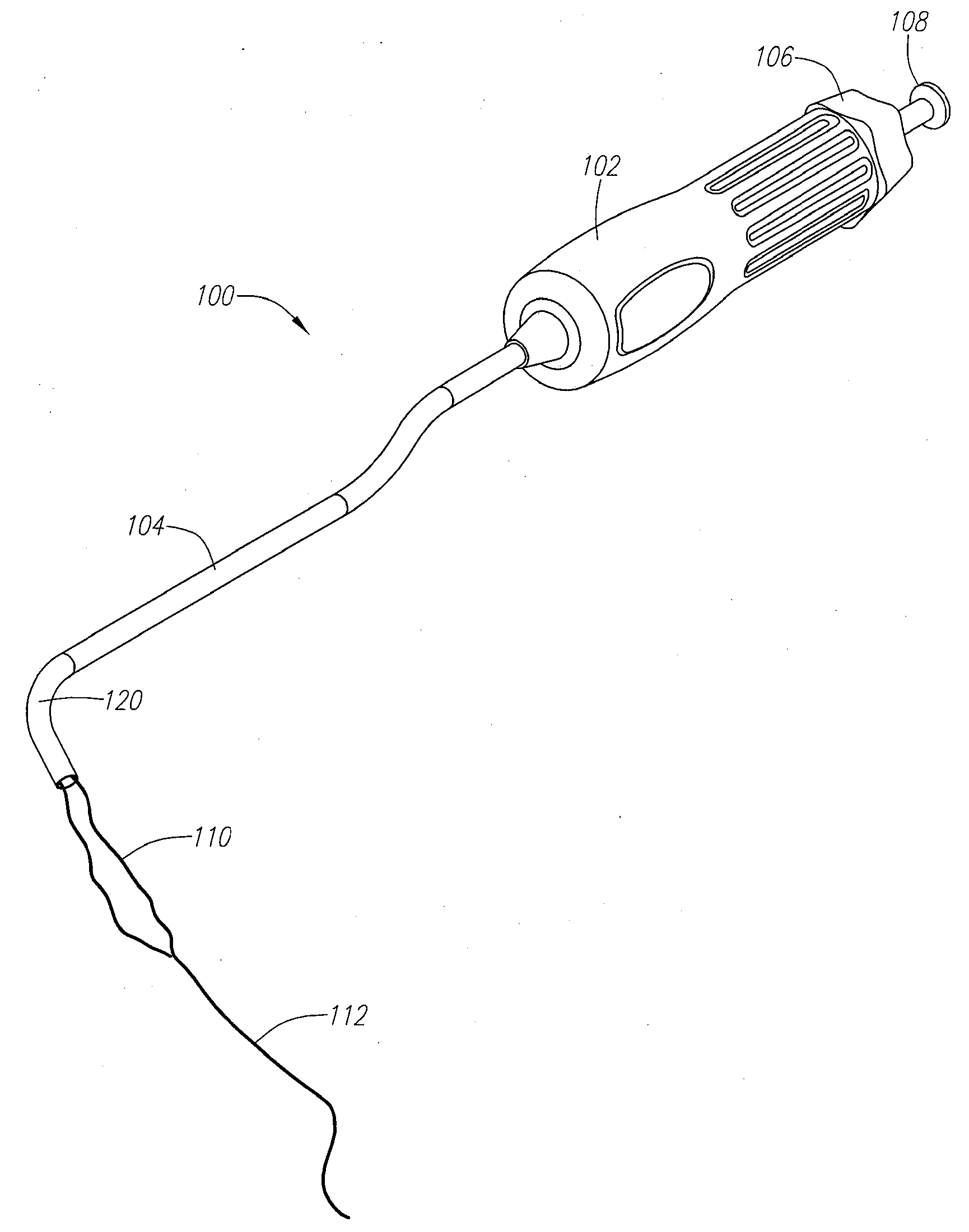
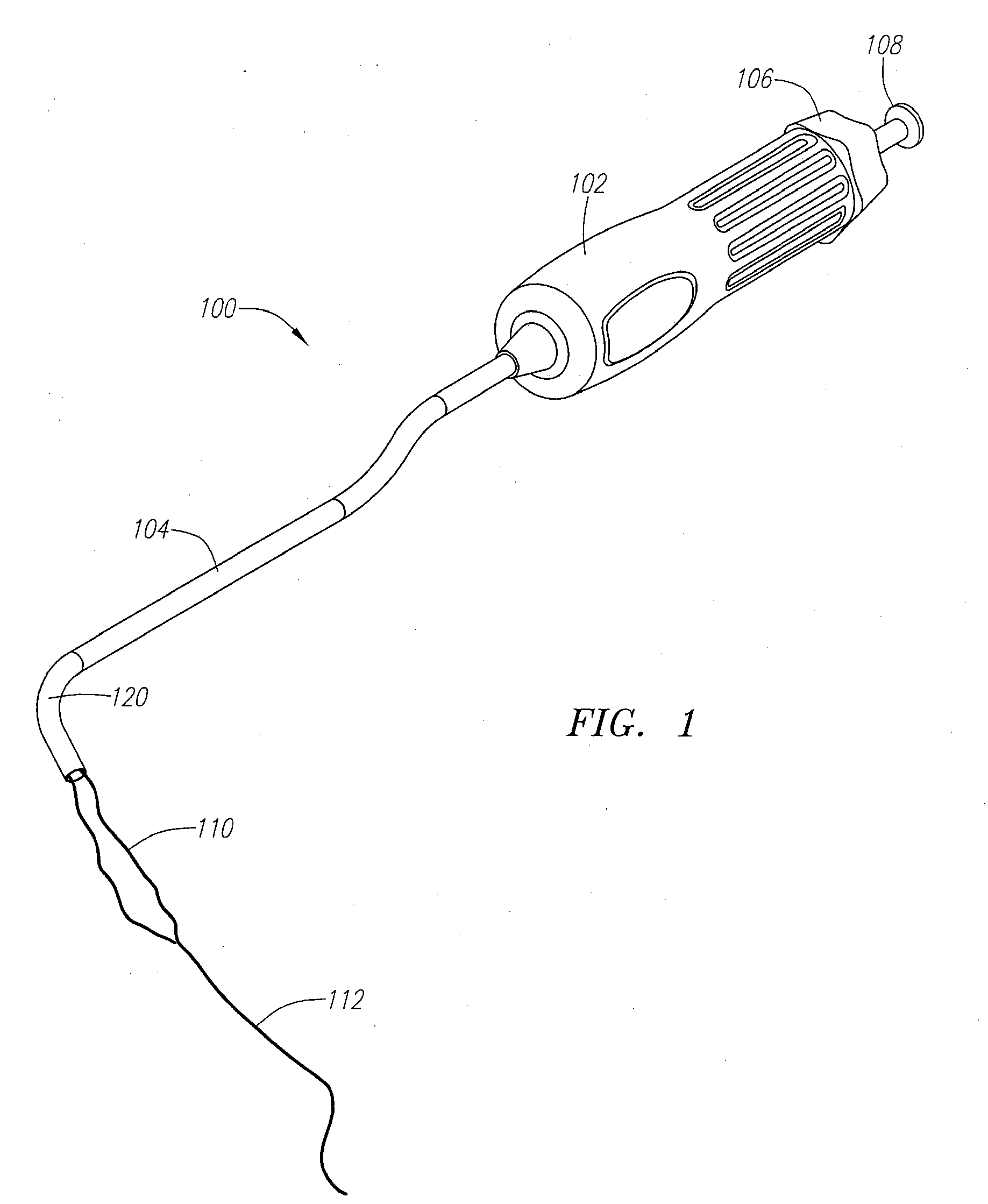
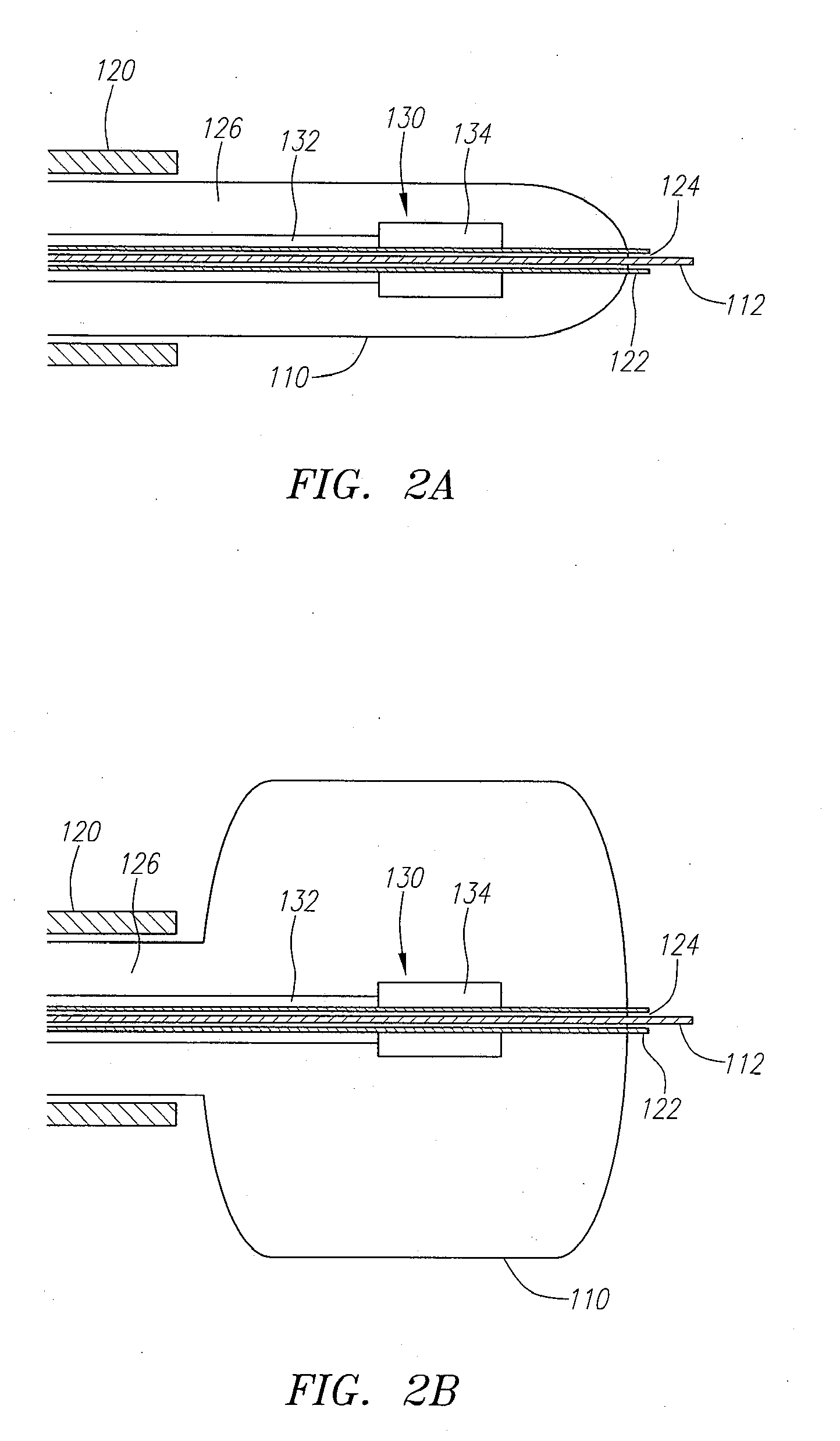
[0052]The present invention is directed to methods and devices for assessing the shape, size, topography, contours, and other aspects of anatomical vessels and organs using minimally invasive surgical techniques. As summarized above, the devices are typically catheter-based devices having one or more assessment mechanisms associated with the distal portion of the catheter. Such devices are suitable for use during less invasive and minimally invasive surgical procedures. However, it should be understood that the devices and methods described herein are also suitable for use during surgical procedures that are more invasive than the preferred minimally invasive techniques described herein.

[0053]Before the present invention is described, it is to be understood that this invention is not limited to particular embodiments described, as such may, of course, vary. It is also to be understood that the terminology used herein is for the purpose of describing particular embodiments only, and ...


PUM


Abstract

Devices and methods for assessing the size, shape, and topography of vessel lumens and hollow portions of organs are described. The devices and methods are particularly adapted for determining the size, shape, topography, and compliance of the native heart valves to facilitate the later implantation of a prosthetic heart valve. The devices are typically catheter-based having an assessment mechanism fixed to a distal end of the catheter. The assessment mechanism generally includes an expandable member, such as a balloon. The assessment mechanism may also include an imaging member, a physical assessment member, an electronic mapping construction, an alignment mechanism, a valvuloplasty balloon, or any combinations thereof. The methods typically comprise deploying the balloon percutaneously to a target location, expanding the balloon, and determining one or more physical parameters associated with the target location.

Description

CROSS-RELATED APPLICATIONS[0001]This application is a divisional of co-pending U.S. patent application Ser. No. 11 / 420,189, filed May 24, 2006, which is fully incorporated herein by reference. U.S. application Ser. No. 11 / 420,189 also relates to U.S. patent application Ser. No. 11 / 066,126, filed Feb. 25, 2005, which claims the benefit of U.S. Provisional Application Ser. No. 60 / 548,731, filed Feb. 27, 2004, and U.S. Provisional Application Ser. No. 60 / 559,199, filed Apr. 1, 2004, all of which are fully incorporated herein by reference.FIELD OF THE INVENTION[0002]The present invention relates generally to medical devices and methods. More particularly, the present invention relates to methods and devices for assessing the shape, size, topography, compliance, and other aspects of cardiac valves and surrounding tissue. The devices and methods are particularly adapted for use during minimally invasive surgical interventions, but may also find application during surgical replacement on a...

Claims


Application Information

Patent Timeline
Patent Type & Authority Applications(United States)
IPC IPC(8): A61B5/05A61B8/15
CPCA61B5/0536A61B5/0538A61B5/1076A61B5/6853A61B5/6885A61B19/54Y10S623/913Y10S623/901Y10S623/90Y10S623/904Y10S623/902Y10S623/903Y10S623/91A61F2/2496A61B90/39
Inventor FORSTER, DAVID C.BECKEY, BRIANWALSH, BRANDONHENEVELD, SCOTT
Owner PHOENIX BIOMEDICAL
Why Eureka
Try Eureka