Ultrasonic diagnosis device and ultrasonic probe for use in ultrasonic diagnosis device

a diagnostic device and ultrasonic technology, applied in the field of ultrasonic diagnostic devices and ultrasonic probes, can solve the problems of difficult to completely cure hardened arteries, difficult to obtain accurate elasticity characteristics of blood vessels, and loss of resilience of arteries, etc., to achieve accurate elasticity characteristics, suppress the generation of measurement errors caused by the movement of blood vessels, and the effect of accurate elasticity characteristics

Inactive Publication Date: 2010-08-26
KONICA MINOLTA INC
View PDF9 Cites 50 Cited by
  • Summary
  • Abstract
  • Description
  • Claims
  • Application Information

AI Technical Summary

Benefits of technology

[0066]According to the present invention, while a property of a blood vessel is measured, the driving device of the ultrasonic diagnostic apparatus moves the transducer based on a control signal from the ultrasonic diagnostic apparatus to change at least one of a direction and a position at which the ultrasonic wave is to be transmitted. The determination section of the ultrasonic diagnostic apparatus specifies a position of the transducer at which the reflection intensity is maximum based on the intensity information representing the intensity of the reflected wave. Owing to this, the positional relationship between the ultrasonic diagnostic apparatus and the blood vessel can be adjusted such that the acoustic line from the ultrasonic transducer passes the center of the cross-section of the blood vessel for measuring the elasticity characteristic. By calculating the elasticity characteristic of the blood vessel at that position, the elasticity characteristic of the blood vessel can be obtained accurately.
[0067]Also according to the present invention, the measurement position determination section controls the probe control section to measure the intensity of the first receiving signal while changing the position of the transducer at each cardiac cycle. Based on the measured intensity, the measurement position determination section also estimates the position change of the axis of the blood vessel during one cardiac cycle and controls the probe control section such that the position of the transducer changes so as to match the estimated position change. Therefore, even where the blood vessel is translated in parallel to the axis thereof, generation of a measurement error caused by the movement of the blood vessel can be suppressed with a relatively simple circuit configuration with no need to analyze the movement of the blood vessel three-dimensionally, and an accurate elasticity characteristic can be found.

Problems solved by technology

How to prevent and treat such diseases is an important issue.
Specifically, where atheroma is formed on a blood vessel wall or new cells of an artery stop being generated due to any of various factors such as high blood pressure and the like, the artery loses resilience thereof and becomes hard and brittle.
However, this method of diagnosis requires the vascular catheter to be inserted into the blood vessel and has a problem of imposing a heavy bodily burden on a test subject.
However, these levels do not directly indicate the progress level of arteriosclerosis.
However, once the arteriosclerosis progresses, it is considered to be difficult to completely cure the hardened artery by a therapeutic drug although a further progress could be suppressed by the drug.
The ultrasonic diagnostic apparatus described in Patent Document No. 3 does not include means for measuring the displacement (distortion) of the blood vessel and so cannot measure the elasticity characteristic thereof.
The processing of providing such a display is time-consuming and cannot avoid increasing the cost.

Method used


Image

  • Ultrasonic diagnosis device and ultrasonic probe for use in ultrasonic diagnosis device
  • Ultrasonic diagnosis device and ultrasonic probe for use in ultrasonic diagnosis device
  • Ultrasonic diagnosis device and ultrasonic probe for use in ultrasonic diagnosis device

Examples


embodiment 1

[0169]Hereinafter, an ultrasonic diagnostic apparatus in Embodiment 1 according to the present invention will be described.

[0170]FIG. 5 is a block diagram showing an internal structure of the ultrasonic diagnostic apparatus 11 in this embodiment.

[0171]The ultrasonic diagnostic apparatus 11 includes a transmission section 14, a receiving section 15, a delay time control section 16, a phase detection section 17, a filtering section 18, a calculation section 19, a calculation data storage section 20, a display section 21, an intensity information generation section 23, a central position determination section 24, and a probe control section 25.

[0172]The ultrasonic diagnostic apparatus 11 also includes a control section 26 formed of a microcomputer or the like in order to control these elements.

[0173]Among the elements of the ultrasonic diagnostic apparatus 11, the intensity information generation section 23, the central position determination section 24, and the probe control section 2...

embodiment 2

[0220]Hereinafter, an ultrasonic diagnostic apparatus in Embodiment 2 according to the present invention will be described.

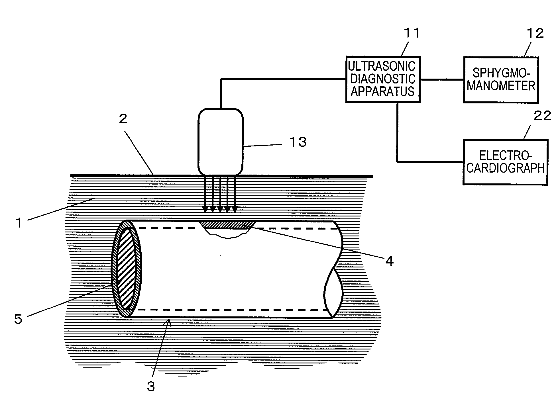
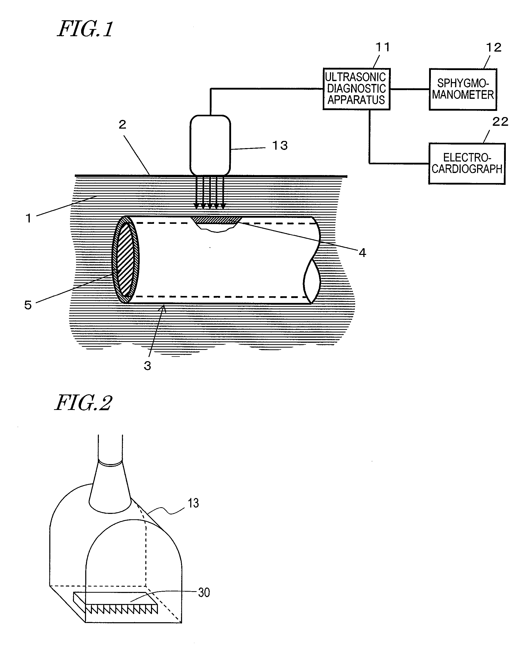
[0221]In Embodiment 1, the transducer 30 is moved within the ultrasonic probe 13 to specify the central position at which the ultrasonic wave passes the center of the cross-section of the blood vessel, with a premise that the direction in which the ultrasonic transducer elements are arranged (for example, the x-axis direction in FIG. 4) is substantially parallel to the longer axis of the blood vessel 3.

[0222]However, when the apparatus is operated by an unaccustomed user, the arranging direction of the ultrasonic transducer elements may be possibly deviated from the longer axis direction of the blood vessel 3 and it cannot be easily expected that the deviation is quickly corrected.

[0223]In this embodiment, an ultrasonic diagnostic apparatus capable of specifying the central position of the blood vessel and accurately measuring the elasticity characteristic even ...

embodiment 3

[0264]Hereinafter, an ultrasonic diagnostic apparatus in Embodiment 3 according to the present invention will be described.

[0265]The ultrasonic diagnostic apparatus in this embodiment has the same structure as the ultrasonic diagnostic apparatus 11 (FIG. 5) in Embodiment 1, and so will be described with reference to the ultrasonic diagnostic apparatus 11 shown in FIG. 5 and the elements thereof.

[0266]In Embodiment 1, the x axis of the transducer 30 (for example, FIG. 4) and the longer axis of the blood vessel 3 along the extending direction of the blood vessel 3 are located substantially parallel to each other.

[0267]In this embodiment, the x axis of the transducer 30 (for example, FIG. 4) and the longer axis of the blood vessel 3 along the extending direction of the blood vessel 3 are located substantially “perpendicular” to each other.

[0268]In such a situation, the intensity information generation section 23 of the ultrasonib diagnostic apparatus (FIG. 5) in this embodiment sequent...


PUM


Abstract

A structure for adjusting the positional relationship between an ultrasonic transducer and a blood vessel such that an acoustic line from the ultrasonic transducer passes the center of a cross-section of the blood vessel for measuring an elasticity characteristic is provided.An ultrasonic probe includes a transducer for transmitting an ultrasonic wave and receiving the ultrasonic wave reflected by a tissue of a biological body; and a driving device for physically moving the transducer. For measuring the elasticity characteristic of the blood vessel by an ultrasonic diagnostic apparatus, the driving device moves the transducer based on a control signal from the ultrasonic diagnostic apparatus to change at least one of a direction and a position at which the ultrasonic wave is to be transmitted. A determination section of the ultrasonic diagnostic apparatus specifies a position of the transducer at which the reflection intensity is maximum based on intensity information representing an intensity of the reflected wave. A calculation section of the ultrasonic diagnostic apparatus calculates the elasticity characteristic of the blood vessel at the specified position.

Description

TECHNICAL FIELD[0001]The present invention relates to an ultrasonic diagnostic apparatus and an ultrasonic probe for medical uses, and specifically to an ultrasonic diagnostic apparatus for measuring properties of a tissues of a biological body and a method for controlling the same, a structure and a method for controlling an ultrasonic probe usable for the ultrasonic diagnostic apparatus, and an ultrasonic diagnostic apparatus for measuring a blood vessel wall.BACKGROUND ART[0002]Recently, the number of the people suffering from circulatory diseases such as myocardial infarction and cerebral infarction has been increasing. How to prevent and treat such diseases is an important issue. To the onset of myocardial infarction and cerebral infarction, arteriosclerosis is deeply involved. Specifically, where atheroma is formed on a blood vessel wall or new cells of an artery stop being generated due to any of various factors such as high blood pressure and the like, the artery loses resil...

Claims


Application Information

Patent Timeline
Patent Type & Authority Applications(United States)
IPC IPC(8): A61B8/14A61B8/00
CPCA61B5/02007A61B8/585A61B8/08A61B8/485A61B8/543G01S7/52042G01S15/8925G01S15/8938G10K11/352G01S15/8918G01S15/8936A61B8/085A61B8/0858A61B8/0891A61B8/4461A61B8/5223A61B8/54A61B8/565A61B5/489A61B8/4444
Inventor KADOKURA, MASAHIKOKATO, MAKOTO
Owner KONICA MINOLTA INC
Why Eureka
Try Eureka