Method of cooling a metal strip traveling through a cooling section of a continuous heat treatment line, and an installation for implementing said method

a technology of continuous heat treatment and cooling section, which is applied in the field of cooling a metal strip, can solve the problems of inability to meet the desired surface quality,

Active Publication Date: 2010-09-02
COCKERILL MAINTENANCE & INGIE
View PDF20 Cites 9 Cited by
  • Summary
  • Abstract
  • Description
  • Claims
  • Application Information

AI Technical Summary

Benefits of technology

[0011]By using an endothermic process with phase change, a large amount of energy is transferred in a manner that depends little on the speed of blowing, thereby making it possible to avoid the above-mentioned risk of setting the metal strip that is being cooled into vibration and / or oscillation. Naturally, the amount of energy transferred depends on the type of refrigerant medium used, and above all on the quantity blown in, and thus on the quantity evaporated or sublimed as a result of the phase change that takes place in the vicinity of the surface of the strip. Furthermore, the above-mentioned drawbacks of the prior art using water as a cooling fluid are avoided.
[0014]In practice, the use of a refrigerant fluid appears to be preferable, not only in terms of performance, but also for greater ease of implementing and controlling the associated installation.
[0016]Advantageously, the sublimed refrigerant solid or the evaporated refrigerant fluid is recovered downstream from the cooling section so as to be recirculated, being subjected to a condensation and separation process at the end of which an incondensable fraction is isolated, said fraction being controlled to adjust the condensation temperature of the refrigerant fluid or solid in order to minimize energy consumption.

Problems solved by technology

Nevertheless, there are practical limits on increasing the blowing speed and on reducing the distance between the strip and the blowing system, since beyond a certain threshold vibration and / or oscillation of the strip appears, and that can lead to the strip coming into contact with the blowing system, thereby leading to marks that are incompatible with the desired surface quality, and possibly even damaging the strip more severely.
The first drawback is that heat transfer is limited by the saturation temperature of water in the incondensable air or nitrogen gas, and the second drawback is that steel at high temperature inevitably suffers oxidation when cooled by a mist of water and air or of water and nitrogen, which means that it is subsequently necessary to perform special treatment for removing an oxide film, where such treatment can be expensive and sometimes even impossible to perform on certain lines such as galvanizing lines.

Method used


Image

  • Method of cooling a metal strip traveling through a cooling section of a continuous heat treatment line, and an installation for implementing said method
  • Method of cooling a metal strip traveling through a cooling section of a continuous heat treatment line, and an installation for implementing said method

Examples


Embodiment Construction

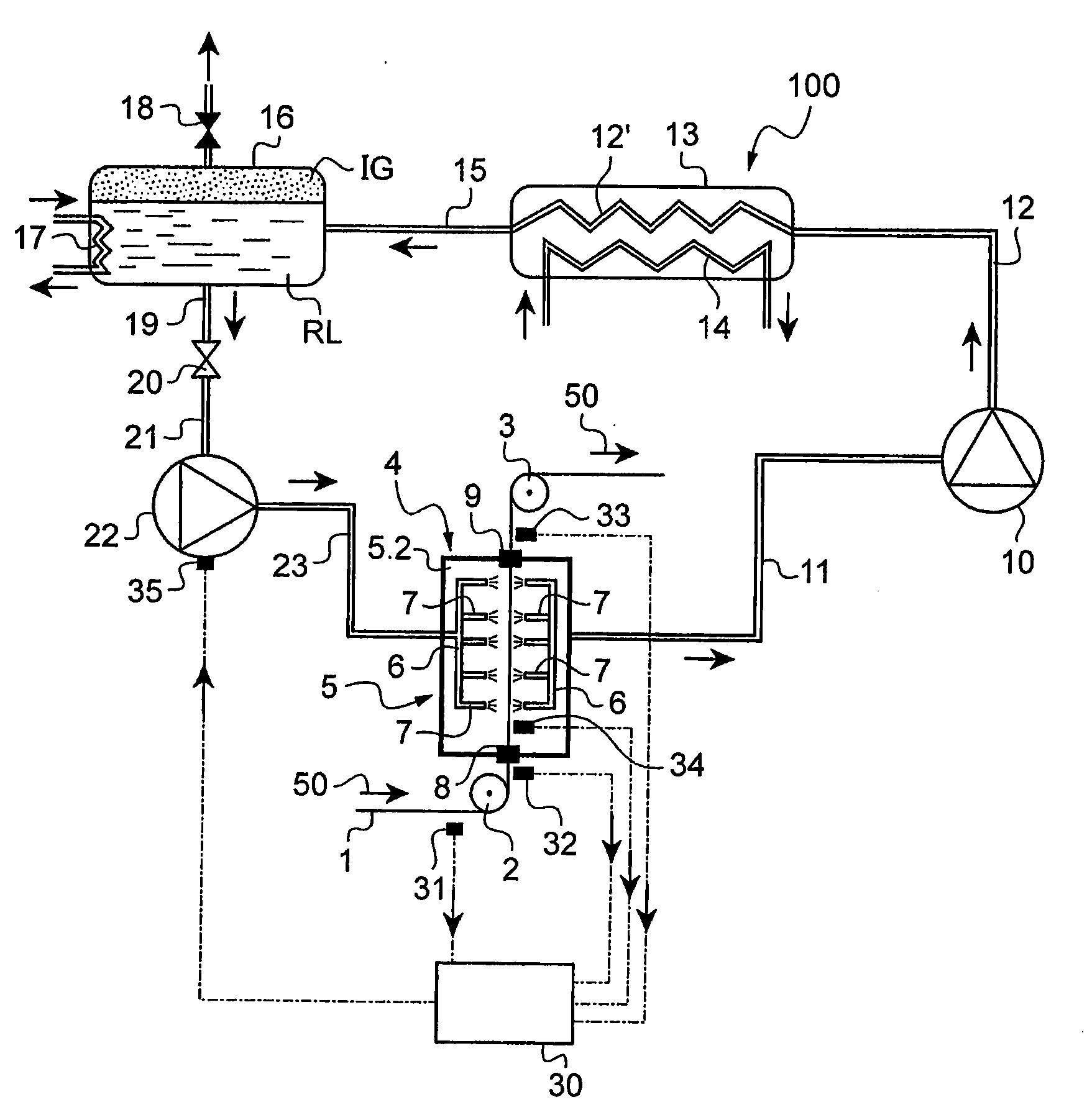
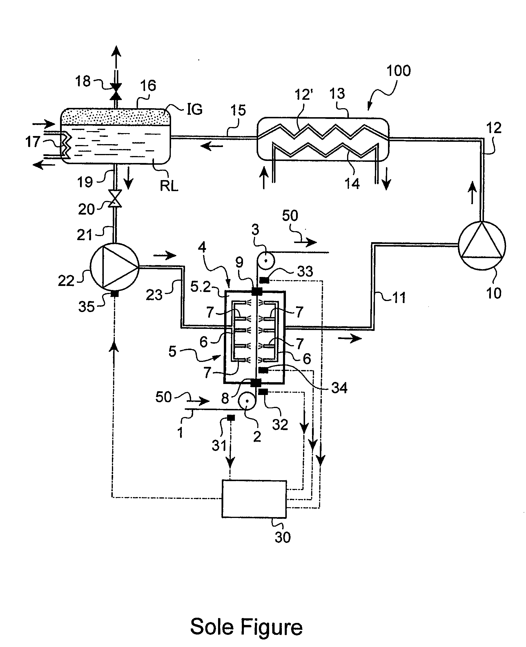
[0034]The sole FIGURE is a diagram showing an installation referenced 100 for implementing the cooling method in accordance with the invention. A metal strip referenced 1 travels through a cooling section referenced 4 in a continuous heat treatment line that may be an annealing line or a line for applying a metal or an organic coating.

[0035]In accordance with the technological background, the line along which the strip 1 passes is determined by a bottom deflector roller 2 and a top deflector roller 3 on either side of the cooling section 4, with the travel direction of the strip 1 being represented by arrows 50.

[0036]The cooling section 4 comprises a cooling box 5 through which the strip 1 for cooling passes. The cooling box 5 is closed and the strip passes in leaktight manner through inlet and outlet airlocks 8 and 9 that are shown diagrammatically. They may be constituted by systems of flaps optionally co-operating with bearing rollers, as is well known in the field of continuous ...


PUM

PropertyMeasurementUnit
temperaturesaaaaaaaaaa
boiling temperatureaaaaaaaaaa
temperatureaaaaaaaaaa

Abstract

The invention relates to a method of cooling a metal strip traveling through a cooling section in a continuous heat treatment line. In accordance with the invention, the method consists in projecting a refrigerant medium into the cooling section (4) onto the surface of the strip (1) to be cooled, the medium being constituted for the most part by a phase-change substance that passes into the gaseous phase at a temperature that is lower than the temperature of the strip (1) and without oxidizing said strip so that energy is exchanged within an endothermic process by a change in the phase of said phase-change substance.

Description

BACKGROUND OF THE INVENTION[0001]The present invention relates to cooling a metal strip traveling through a cooling section in a continuous heat treatment line, such as an annealing line or a line for applying a metal or an organic coating.[0002]In continuous heat treatment lines of the above-mentioned type, metal strips are cooled in a cooling section by blowing a gas, generally a mixture of nitrogen and hydrogen, through one or more cooling boxes that are fitted with associated holes or blow tubes.[0003]A constant concern of designers of cooling sections lies in cooling the strip traveling through said section as uniformly as possible, while simultaneously avoiding giving rise to instabilities and / or vibration in the traveling strip.[0004]Document EP-A-1 655 383 discloses such a cooling device, in which a strip travels between two cooling boxes fitted with blow tubes inclined at an angle that is directed upstream and / or downstream relative to the traveling strip, and also towards ...

Claims


Application Information

Patent Timeline
Patent Type & Authority Applications(United States)
IPC IPC(8): F25D3/10F25D3/12F25D17/04F28D21/00
CPCC21D9/573F27D9/00F27B9/12F25D3/12
Inventor NEMER, MAROUNZOGHAIB, MARIACLODIC, DENISABDO, DIALALANGEVIN, STEPHANEDUBOIS, PATRICK
Owner COCKERILL MAINTENANCE & INGIE
Why Eureka
Try Eureka