Substrate processing apparatus and substrate processing method

Active Publication Date: 2010-09-02
TOKYO ELECTRON LTD
View PDF9 Cites 9 Cited by
  • Summary
  • Abstract
  • Description
  • Claims
  • Application Information

AI Technical Summary

Benefits of technology

[0027]According to such a substrate processing apparatus and such a substrate processing method, the drying is firstly supplied into the drying chamber, and the supply of the drying gas into the drying chamber is stopped before the substrate to be processed is drawn up from the cleaning tank into the drying chamber. Thus, when the substrate to be processed is moved into the drying chamber, the drying chamber has been already filled with the drying gas atmosphere, and the liquid film of the drying gas has been formed on the cleaning liquid in the cleaning tank. Thus, it is possible to reduce a time period between a timing when the drawing-up of the substrate to be processed from the cleaning liquid in the cleaning tank is started and a timing when the drying gas is supplied onto the surface of the substrate to be processed. Thus, it is possible to uniformly and promptly dry the surface of the substrate to be processed, and to restrain formation of watermarks on the surface of the substrate to be processed by droplets of the cleaning liquid adhering to the surface of the substrate to be processed.
[0028]In addition, when the substrate to be processed is drawn up from the cleaning liquid in the cleaning tank, since the drying gas is supplied in the substantially horizontal direction, the obliquely downward direction descendent from the substantially horizontal direction, or the vertically downward direction, the liquid film of the drying gas, which has been as described above, can be formed on the cleaning liquid in the cleaning tank. In addition, since the drying gas is supplied in the substantially horizontal direction, the obliquely downward direction descendent from the substantially horizontal direction, or the vertically downward direction, there is no possibility that the drying gas of relatively a high temperature is directly blown onto the upper wall constituting the drying chamber, whereby wate

Problems solved by technology

Thus, there is a possibility that the surface of the wafer might not be uniformly dried, resulting in formation of watermarks on the surface of the wafer which might be caused by droplets of the cleaning liquid adhering to the surface of t

Method used


Image

  • Substrate processing apparatus and substrate processing method
  • Substrate processing apparatus and substrate processing method
  • Substrate processing apparatus and substrate processing method

Examples


Embodiment Construction

[0040]An embodiment of the present invention will be described in detail below with reference to the drawings. Given herein as an example to describe this embodiment is a case where the present invention is applied to a cleaning system for semiconductor wafers.

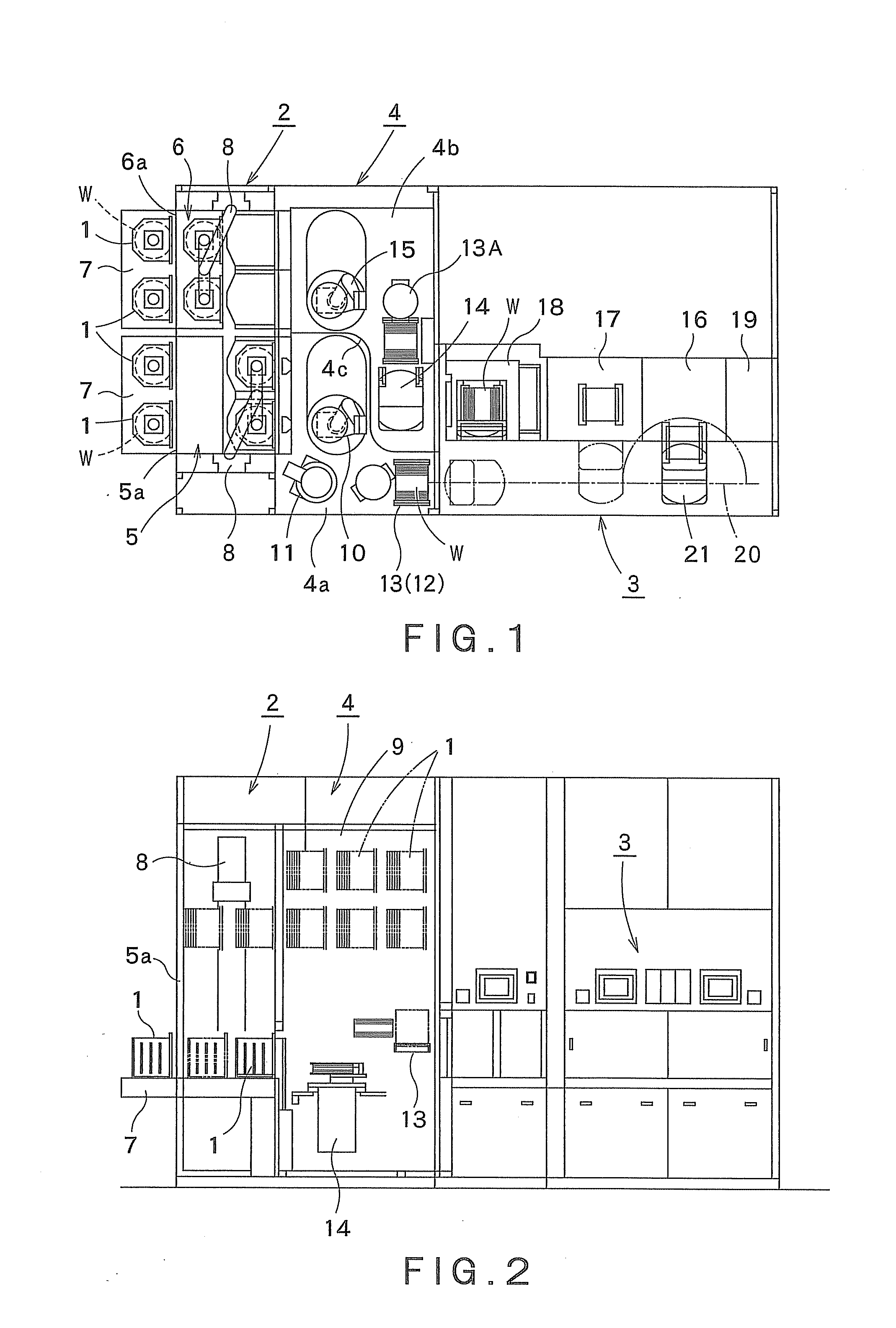
[0041]FIG. 1 is a schematic plan view showing an example of the cleaning system to which the substrate processing apparatus according to the present invention is applied. FIG. 2 is a schematic side view thereof.

[0042]The cleaning system shown in FIGS. 1 and 2 is mainly composed of: a transfer part 2 configured to load and unload a container, such as a carrier 1, which horizontally accommodates semiconductor wafers W (hereinafter referred to as “wafers”) as objects to be processed; a processing part 3 configured to liquid-process wafers W by a chemical liquid and / or a cleaning liquid, and to dry the wafers W; and an interface part 4 interposed between the transfer part 2 and the processing part 3, the interface part 4 being con...


PUM


Abstract

A drying gas is supplied into a drying chamber in a substantially horizontal direction, an obliquely downward direction descendent from the substantially horizontal direction, or a vertically downward direction under a state where a wafer is immersed in a cleaning liquid in a cleaning tank. The wafer is moved from the cleaning tank into the drying chamber, with the drying gas being supplied into the drying chamber. At this time, the supply of the drying gas into the drying chamber is stopped, under a condition where a part of the wafer is immersed in the cleaning liquid stored in the cleaning tank. After the movement of the wafer into the drying chamber has been finished, a drying gas is supplied into the drying chamber in an obliquely upward direction ascendant from the substantially horizontal direction or a vertically upward direction.

Description

FIELD OF THE INVENTION[0001]The present invention relates to a substrate processing apparatus and a substrate processing method, which immerse a substrate to be processed, such as a semiconductor wafer or an LCD glass substrate, into a cleaning liquid such as a chemical liquid or a rinse liquid, and thereafter dry the substrate to be processed. More particularly, the present invention relates to a substrate processing apparatus and a substrate processing method, which are capable of uniformly and promptly drying the surface of the substrate to be processed.BACKGROUND ART[0002]In a general manufacturing process of a semiconductor manufacturing apparatus, there has been widely employed a cleaning method in which a substrate to be processed (hereinafter referred to as “wafer”), such as a semiconductor wafer or an LCD glass, is cleaned in a sequential order by immersing the wafer into a cleaning tank storing a cleaning liquid such as a chemical liquid or a rinse liquid. In addition, the...

Claims


Application Information

Patent Timeline
IPC IPC(8): B08B3/00
CPCH01L21/67028H01L21/02052
Inventor TANAKA, HIROSHISHIOKAWA, TOSHIYUKIINADA, TAKAO
Owner TOKYO ELECTRON LTD
Why Eureka
Try Eureka