Low-voltage, medium-voltage or high-voltage switchgear assembly having a short-circuiting system

a switchgear assembly and short-circuiting technology, which is applied in the direction of air-break switches, high-tension/heavy-dress switches, and explosion switches closing

Active Publication Date: 2010-09-02
ABB (SCHWEIZ) AG
View PDF5 Cites 21 Cited by
  • Summary
  • Abstract
  • Description
  • Claims
  • Application Information

AI Technical Summary

Benefits of technology

[0012]An exemplary embodiment provides a switchgear assembly which comprises a vacuum interrupt chamber, and at least one short-circuiting device arranged in the vacuum interrupt chamber. The at least one short-circuiting device includes a fixed contact piece arranged in a vacuum area of the vacuum interrupter chamber, a moving contact piece, and a unit for causing the moving contact piece to close onto the fixed contact piece. In addition, the at least one short-circuiting device includes a membrane sub-dividing the vacuum area in which the fixed contact piece is arranged. The membrane has a breaking line which is configured to be penetrated during a switching operation when the moving contact piece is moved through the membrane and closed onto the fixed contact piece.

Problems solved by technology

A fault arc which occurs within a switchgear assembly would produce a sharp pressure rise of the gas, due to the temperature of the gas, within a time period of a few milliseconds, which can lead to the switchgear assembly being destroyed by explosion.
The effects of a fault arc can therefore be limited by reducing the arc duration.
However, this arrangement has the disadvantage that the greatest mechanical load occurs just after approximately 10 ms, and only the thermal load is reduced.
This arrangement involves a generally robust and costly configuration of the design of a switchgear assembly, of encapsulation or of a solid-insulated system.
In any case, the switching rating and isolation capability are reduced because of the high inrush current on repeated switching.
However, there are drawbacks associated with the second and third cited prior art references for switchgear assemblies, including medium-voltage switchgear assemblies, for example.
In conjunction with the upstream circuit breaker, known short-circuiting devices switch too slowly.
Because of their three-phase design, they are generally also technically too complicated and costly.
Furthermore, the current results in a decrease in the switching rating and the isolation capability over the lifespan of the short-circuit devices.

Method used


Image

  • Low-voltage, medium-voltage or high-voltage switchgear assembly having a short-circuiting system
  • Low-voltage, medium-voltage or high-voltage switchgear assembly having a short-circuiting system
  • Low-voltage, medium-voltage or high-voltage switchgear assembly having a short-circuiting system

Examples


Embodiment Construction

[0017]Exemplary embodiments of the present disclosure provide a switchgear assembly having a short-circuiting device which overcomes the described disadvantages of the prior art, and allows rapid switching with physically simple means.

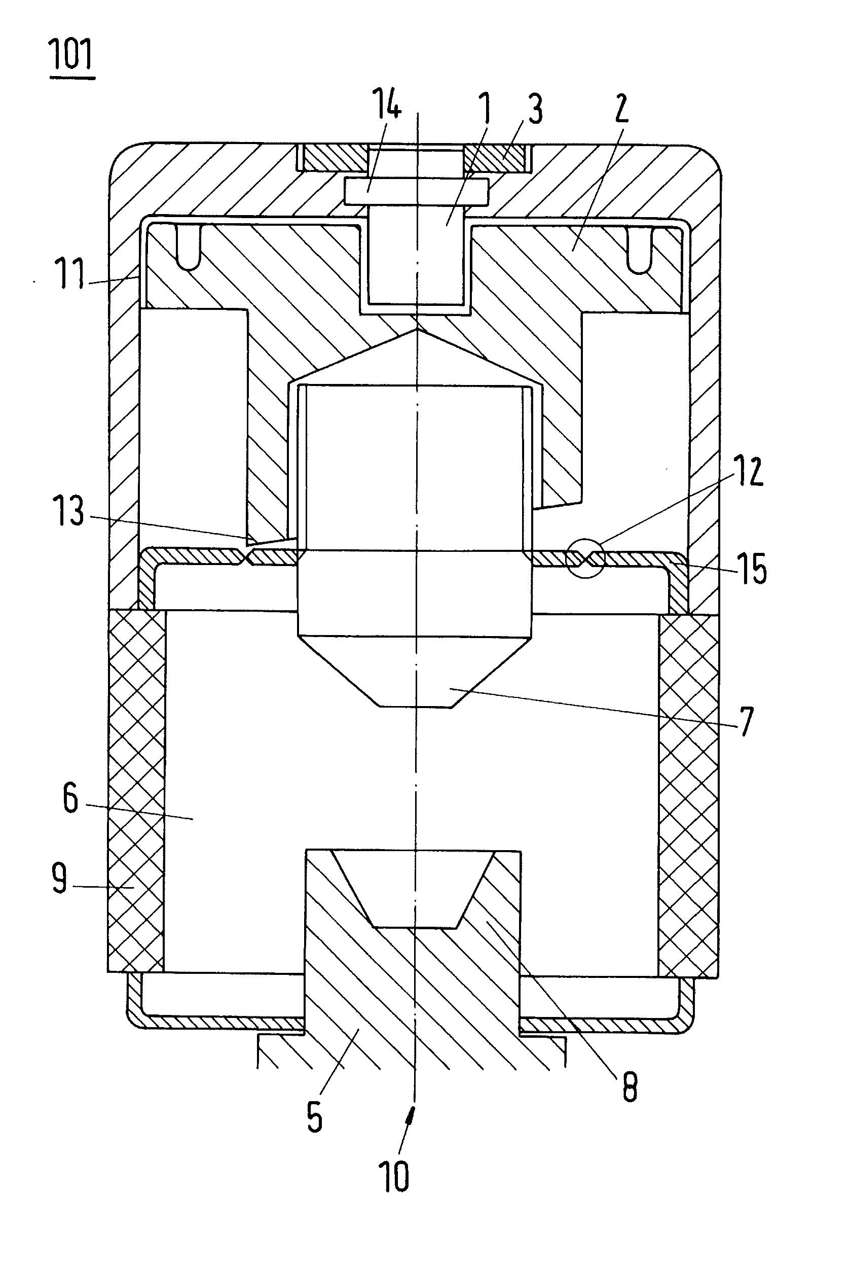
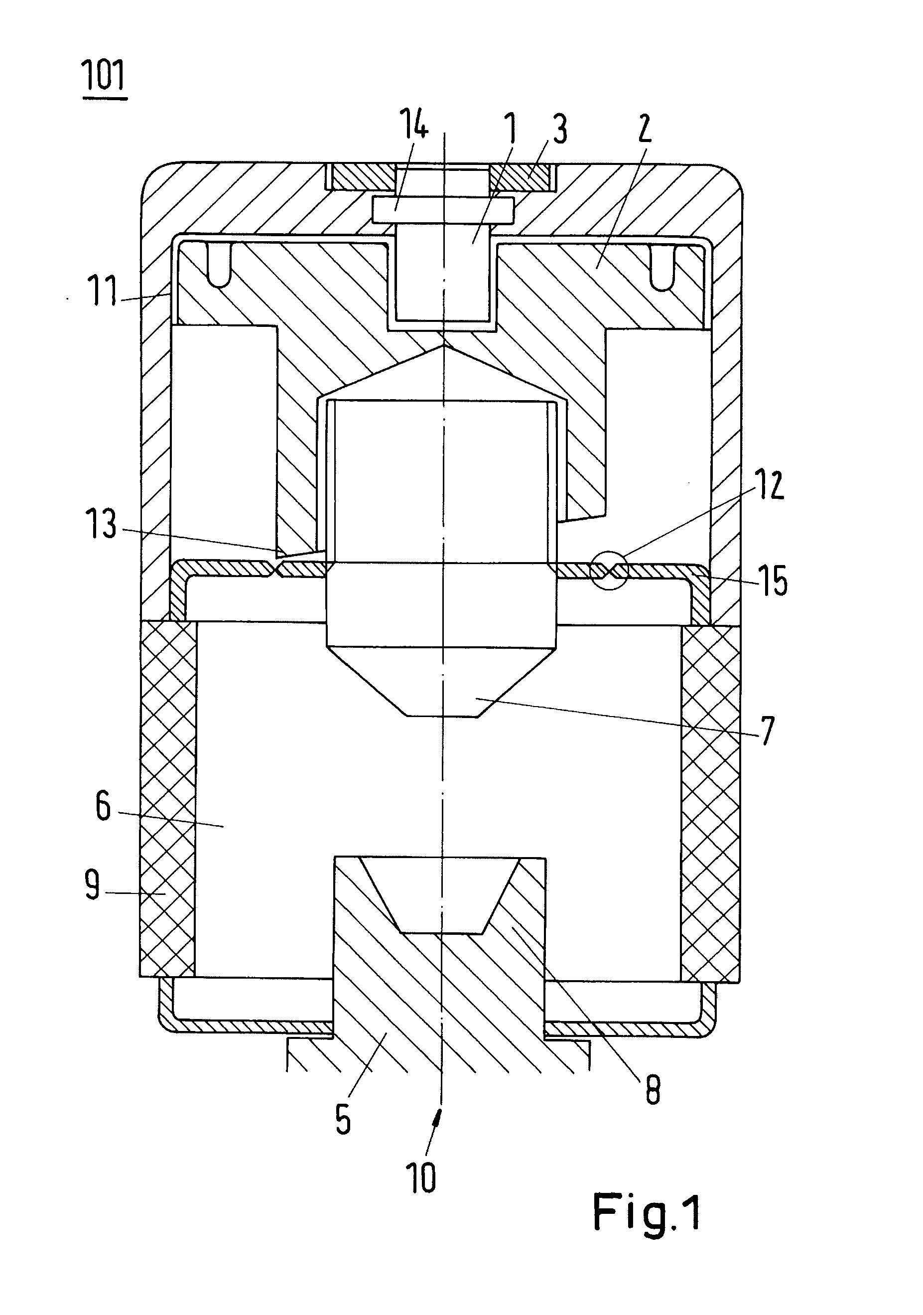
[0018]According to an exemplary embodiment of the present disclosure, a short-circuiting device is arranged in a vacuum interrupter chamber, and the vacuum area in which the fixed contact piece is placed is subdivided via a membrane which is provided with a weak breaking line. An appropriately designed piston above the moving contact piece (in the form of a plug or a socket, likewise arranged in the vacuum of the switching chamber) will penetrate the membranes in the area of the weak point during switching, moving the unit in the direction of the fixed contact. In consequence, there is no need at all for the bellows, which are normally otherwise required, on the moving contact. The penetration movement, which is now all that is needed, advantageously r...


PUM


Abstract

A switchgear assembly includes a vacuum interrupt chamber and a short-circuiting system arranged in the vacuum interrupt chamber. To enable rapid switching with physically simple means, a vacuum area of the vacuum interrupt chamber in which a fixed contact piece is placed is subdivided via a membrane, which is provided with a breaking line and which can be penetrated by a moving piston system to the contact piece during switching. The switchgear assembly can be utilized in a low-voltage, medium-voltage or high-voltage assembly.

Description

RELATED APPLICATIONS[0001]This application claims priority as a continuation application under 35 U.S.C. §120 to PCT / CH2008 / 007121, which was filed as an International Application on Sep. 1, 2008 designating the U.S., and which claims priority to European Application 07017360.4 filed in Europe on Sep. 5, 2007. The entire contents of these applications are hereby incorporated by reference in their entireties.FIELD[0002]The present disclosure relates to a low-voltage, medium-voltage and high-voltage switchgear assembly having a short-circuiting system.BACKGROUND INFORMATION[0003]Low-voltage, medium-voltage and high-voltage switchgear assemblies have the task of distributing the energy flow and of ensuring safe operation. In the improbable case of an internal fault (fault arc), installation safety and personal safety must also be ensured. A fault arc which occurs within a switchgear assembly would produce a sharp pressure rise of the gas, due to the temperature of the gas, within a tim...

Claims


Application Information

Patent Timeline
Patent Type & Authority Applications(United States)
IPC IPC(8): H01H33/66
CPCH01H33/6646H01H79/00H01H39/004H01H33/666
Inventor GENTSCH, DIETMAR
Owner ABB (SCHWEIZ) AG
Why Eureka
Try Eureka