Apparatus and method for heating material by adjustable mode RF heating antenna array

Active Publication Date: 2010-09-02
HARRIS CORP
View PDF100 Cites 23 Cited by
  • Summary
  • Abstract
  • Description
  • Claims
  • Application Information

AI Technical Summary

Benefits of technology

[0009]An aspect of the invention concerns an apparatus for heating a material that is susceptible RF heating by an RF antenna array. The apparatus includes a source of RF power connected to an antenna array having a plurality of loop antenna sections connected to each other by dipole antenna sections wherein the loop sections and dipole sections create a magnetic near field and an electric near field such that the ratio of magnetic field strength to electric field strength is approximately a predetermined value.
[0010]Another aspect of the invention conc

Problems solved by technology

Because of the high viscosity of bituminous ore, oil sands, oil shale, tar sands, and heavy oil, however, the drilling and refinement methods used in extracting standard crude oil are typically not available.
Material extracted from these deposits is viscous, solid or semisolid and does not flow easily at normal temperatures making transportation and processing difficult and expensive.
Conventional methods of heating bituminous ore, oil sands, tar sands, and heavy oil suffer from many drawbacks.
For example, the conventional methods typically a

Method used


Image

  • Apparatus and method for heating material by adjustable mode RF heating antenna array
  • Apparatus and method for heating material by adjustable mode RF heating antenna array
  • Apparatus and method for heating material by adjustable mode RF heating antenna array

Examples


Embodiment Construction

[0017]The present invention will now be described more fully hereinafter with reference to the accompanying drawings, in which one or more embodiments of the invention are shown. This invention may, however, be embodied in many different forms and should not be construed as limited to the embodiments set forth herein. Rather, these embodiments are examples of the invention, which has the full scope indicated by the language of the claims. Like numbers refer to like elements throughout.

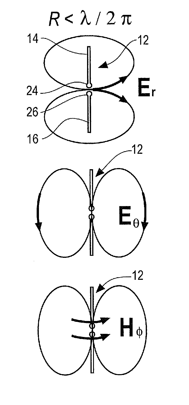
[0018]RF heating occurs in the reactive near field region of an antenna. The electric and magnetic fields in this region depend on the antenna from which RF energy is emitted.

[0019]FIG. 1 illustrates the near field region electric (E) and magnetic (H) fields of a dipole antenna 12. The antenna 12 comprises two separate and oppositely extending sections 14 and 16 that are connected to RF energy at connections located at the separation between them, 24 and 26 respectively. The antenna 12 is generally str...


PUM


Abstract

An apparatus for heating a material that is susceptible to RF heating by an RF antenna array. The apparatus includes a source of RF power connected to an antenna array having a plurality of loop antenna sections connected to each other by dipole antenna sections wherein the loop antenna sections and dipole antenna sections create a magnetic near field and an electric near field such that the ratio of magnetic field strength to electric field strength is approximately a predetermined value. Material is heated by the apparatus by placing the material in the near fields of the antenna array and creating magnetic near fields and electric near fields that approximate a ratio that is predetermined to efficiently heat the material and connecting the antenna array to an RF power source.

Description

STATEMENT REGARDING FEDERALLY SPONSORED RESEARCH OR DEVELOPMENT[0001][Not Applicable]CROSS REFERENCE TO RELATED APPLICATIONS[0002]This specification is related to McAndrews, Held & Malloy attorney docket numbers:Atty. Dkt. No.Ser. No.20476US0112 / 396,24720478US0112 / 395,99520481US0112 / 396,19220483US0112 / 396,02120484US0112 / 396,28420485US0112 / 396,05720486US0112 / 395,95320496US0112 / 395,918filed on the same date as this specification, each of which is incorporated by reference herein.BACKGROUND OF THE INVENTION[0003]The invention concerns heating of materials, and more particularly heating with radio frequency (RF) energy that can be applied to process flows. In particular, this disclosure concerns an advantageous method for RF heating of materials that are susceptible of heating by RF energy by electric dissipation, magnetic dissipation, electrical conductivity and by a combination of two or more of them. In particular, this invention provides a method and apparatus for heating mixtures c...

Claims


Application Information

Patent Timeline
IPC IPC(8): H05B6/04
CPCH05B6/72
Inventor PARSCHE, FRANCIS EUGENE
Owner HARRIS CORP
Why Eureka
Try Eureka