
Bale processing apparatus

a technology of bale processing and bale, which is applied in the field of bale processing equipment, can solve the problems of reducing the efficiency of processing, and reducing so as to reduce the maintenance and wear of equipment, and reduce the amount of waste of energy

Inactive Publication Date: 2010-09-02
WEISS LEONARD D
View PDF7 Cites 12 Cited by
  • Summary
  • Abstract
  • Description
  • Claims
  • Application Information

AI Technical Summary

Benefits of technology

[0012]The forage material in the bale is cut to a desired length (e.g. 3-12 inches) by the cutting blades or knives. Because the forage material is cut into a desired length, it is not ground into fine particles or powder. This avoids the formation of dust which typically results from the use of conventional tub grinders. The efficiency of the processor of this invention results in less horsepower and fuel requirements than are needed for operating other bale processors. There is also less maintenance and wear on the equipment. The types of cutting blades or knives may vary, and the spacing between adjacent blades or knives may also vary, as desired.
[0014]The bale processor can easily handle all types, sizes and shapes of forage material (e.g. small, medium or large square bales; round bales; or loose or loaf hay or straw) and requires significantly less horsepower than conventional processors. The bale processor of the invention also provides a better quality feed ration with longer stems which have good leaf to stem ratio (not just sticks and powder from over-processing). The cutting blades can also be easily changed, when desired, to meet the needs of each farmer, dairy, feedlot commercial grinding or reclamation service. By adding more cutting blades and increasing the run speed, the processor is also useful as a hay grinder.

Problems solved by technology

Unfortunately, this action also results in much of the forage being pulverized into very small pieces, thereby creating a considerable amount of dust which is very undesirable.
Any dust particles which blow or drift away in the wind are lost.
Furthermore, very small particles of forage fed to animals are not desirable as feed.
Thus, the knives he shows are very inefficient in shredding a bale; consequently, he requires the inclusion of an oscillating carriage for oscillating the bale across the cutting knives to induce further cutting action.
Also, Goosen does not provide for dispensing cut material selectively to the left or the right side of the machine.

Method used


Image

  • Bale processing apparatus
  • Bale processing apparatus
  • Bale processing apparatus

Examples


Embodiment Construction

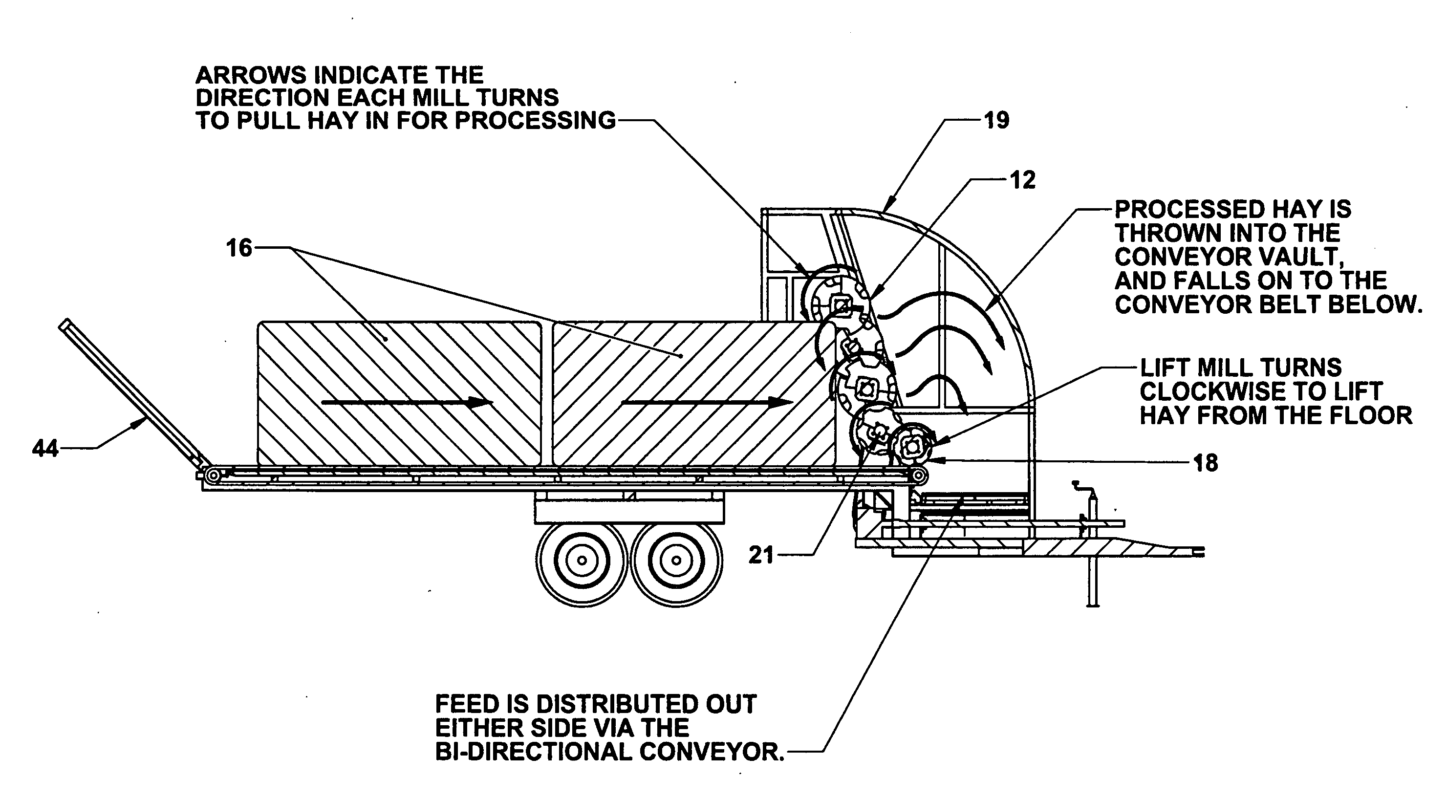
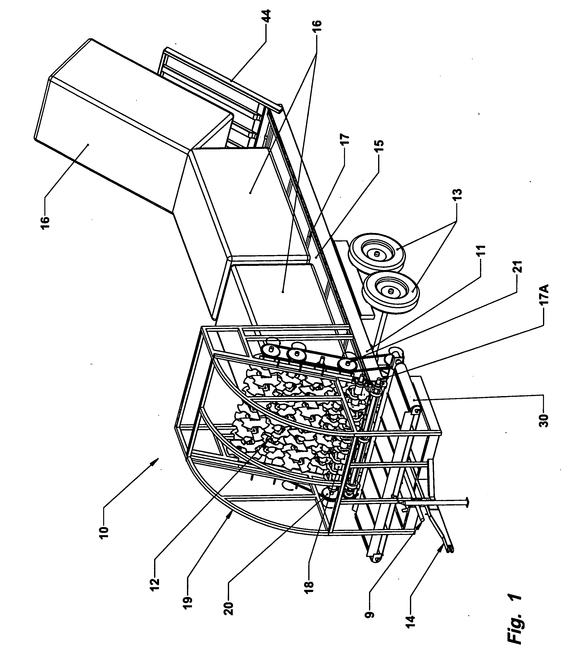
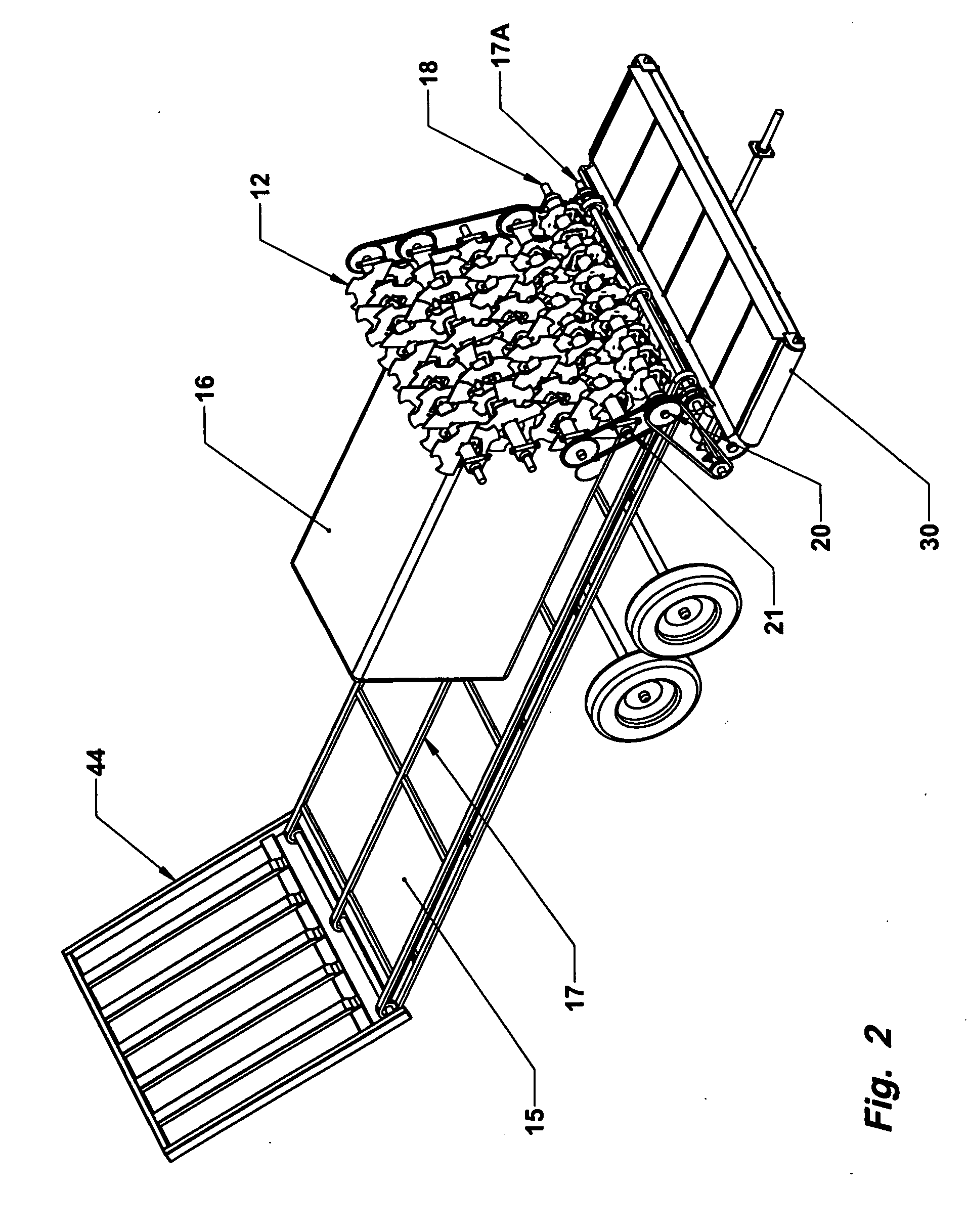
[0034]A preferred embodiment of the bale processor 10 of the present invention is illustrated in FIGS. 1-4. Portions of the front enclosure or shroud 19 normally shielding the mill means 12 on three sides have been removed to more clearly show the mill. The apparatus includes an elongated frame 11, carried on wheels 13, with hitch 14 for towing by a tractor. An elongated bed 15 rests on the frame for supporting large round or square bales 16 to be processed. The elongated bed includes a conveyer chain or apron 17 (driven by shaft 17A) for moving a bale longitudinally along the bed toward the cutting knives in the mill. Instead of using a chain conveyer, it is possible to use a continuous rubber belt. One advantage of using a rubber belt is that it will not become frozen to the bed in very cold temperatures. Also, a continuous belt prevents leaves and other small particles of forage from being lost prior to processing of the material.

[0035]The mill means 12 comprises at least two, an...


PUM


Abstract

Bale processing apparatus is disclosed which includes an elongated bed for supporting bale of forage to be processed. Cutting blades are carried on transverse shafts at one end of the apparatus, and a conveyer advances the bale toward the cutting blades. The lowermost transverse shaft rotates opposite to the next adjacent transverse shaft. The cutting means further include an outwardly projecting blade to assist in cutting the forage material. In one embodiment, the cutting mill is tilted rearwardly.

Description

CROSS-REFERENCE TO RELATED APPLICATIONS [0001]This application is a continuation-in-part of my earlier copending application Ser. No. 11 / 820,309, filed Jun. 19, 2007, which was a continuation-in-part of my earlier application Ser. No. 11 / 243,616, filed Oct. 5, 2005, which was based upon, and claims priority from, my Provisional Application No. 60 / 618,673, filed Oct. 14, 2004.FIELD OF THE INVENTION [0002]This invention relates to equipment used for processing bales of forage such as hay or straw. More particulary, in one embodiment this invention relates to equipment which can be towed behind a tractor, or be truck-mounted, for processing large bales.BACKGROUND OF THE PRIOR ART[0003]It is common for farmers, ranchers, dairies, feedlot operators, etc. to use large bales of forage such as hay or straw when feeding or bedding their animals. Large bales are sometimes also used for mulch when planting grass along roadways, for example, or for land reclamation.[0004]Conventional bale proce...

Claims


Application Information

Patent Timeline
Patent Type & Authority Applications(United States)
IPC IPC(8): B02C18/24B02C19/00B02C18/16
CPCA01K5/005A01F29/005
Inventor WEISS, LEONARD D.
Owner WEISS LEONARD D
Learn More