Roller drill or roller bit

a technology of roller bits and drill bits, which is applied in the direction of earth drilling, cutting machines, slitting machines, etc., can solve the problems of system-related rapid wear of individual roller bits, and achieve the effect of not affecting the sharpening effect of the tool according to the invention

Inactive Publication Date: 2010-09-02
CATERPILLER GLOBAL MINING EURO GMBH
View PDF7 Cites 9 Cited by
  • Summary
  • Abstract
  • Description
  • Claims
  • Application Information

AI Technical Summary

Benefits of technology

[0006]More particularly provided is a cutting face that is made of a harder material than the supporting body and in that the supporting body forms an annular web which runs conically at least at its outer circumferential wall and which defines with its inner circumferential wall a free space at the end face of the tool. The interplay between the dissimilar material combination of hardened or harder cutting face and softer supporting body on the one hand and the free space in the supporting region of the supporting body, i.e. as viewed radially in each case behind the cutting face, on the other hand achieves the situation where the cutting edge at the transition between the cutting face and the end face can resharpen itself automatically over a comparatively long period of time. The self-resharpening effect is achieved in particular by virtue of the fact that, when the hardened cutting face wears down, the softer material of the supporting body located behind said cutting face is also worn away by the rock to be removed, as a result of which only the hardened cutting face is substantially in constant contact with the material to be removed.
[0007]In order to achieve the effect of the automatic resharpening of the tool according to the invention, it is not absolutely necessary for the free space to be designed as a cavity or the like; the free space, in the radial direction behind the supporting body, could also be filled with a material that is even softer than the material of the supporting body. In a preferred configuration, however, the free space in the back of the supporting body is designed as a hollow recess. It is advantageous if the free space extends from the end face of the tool at least partly over the axial extent of the cutting face of the tool. The deeper the free space in the axial direction, the greater is the effective axial length of the cutting face at which automatic resharpening of the cutting edge of the roller bit can be achieved. In addition, the worn-away material of the supporting body can collect temporarily in the cavity behind the supporting body.
[0008]In one embodiment, the annular web has an exactly constant thickness or a substantially constant thickness between its inner circumferential wall and its outer circumferential wall. This configuration has the advantage that the roller drill, introduces, throughout its entire resharpening service life, the same restoring forces into the machine on which the roller drills are used, since, irrespective of the degree of wear, therefore irrespective of the axial shortening of the cutting face made of hardened material, the same cross section of softer supporting body material has to be worn away in order to achieve the situation where only the cutting edge made of harder material is in operative engagement with the rock to be removed. To this end, the inner circumferential wall expediently runs conically, as a result of which the free space or the recess likewise tapers conically toward the root of the free space. According to an advantageous configuration, the cone angle of the inner circumferential wall and the cone angle of the cutting face can be substantially the same. Depending on the material combination used, it may be sufficient if the thickness of the annular web is only approximately constant. In this case, the cone angle of the inner circumferential surface and the cone angle of the cutting face can differ from one another by less than 8°, in particular less than 5°, preferably less than 2°. Depending on the material combination used, the web thickness may also vary, the web thickness as a rule being made usually two to ten times thicker than the radial thickness of the cutting face. On the whole, the web thickness should be made as thin as possible in order for it to be possible for the likewise softer material to be worn away quickly.
[0009]According to the invention, roller bits or roller drills having hardened cutting faces supported radially by means of annular supporting bodies can be constructed in different ways. According to an advantageous configuration, the supporting body has a cylindrical neck section and a conical collar section, which forms the annular web. In one embodiment, the cutting face can then consist of surface hardening or a hard coating applied to the conically running outer circumferential wall of the annular web. Alternatively, the cutting face can consist of cutting segments or carbide segments fastened to the conically running outer circumferential wall of the annular web. The cutting segments or carbide segments can be fastened to, in particular brazed to, or brazed in place on, the outer circumferential wall of the annular web of the supporting body. The use of cutting segments has the advantage that the concentrically encircling cutting face can be produced relatively simply. In order to protect corresponding cutting segments or carbide segments from damage by shock loading or chipping even under the highest axial loads, the cutting segments or carbide segments can be covered by means of at least one ring or a covering layer which is made of a softer material than the cutting face. A corresponding ring or a corresponding covering layer therefore provides for additional fixing of the cutting segments and thus of the cutting face on the supporting body. The material of the ring or of the covering layer is expediently also softer than the material of the annular web, in order that the resharpening effect of the tool according to the invention is not adversely affected.

Problems solved by technology

The axial forces in turn cause, in particular on the cutting edge at the free margin of the cutting face, system-related rapid wear of the individual roller bits.

Method used


Image

  • Roller drill or roller bit
  • Roller drill or roller bit
  • Roller drill or roller bit

Examples


Embodiment Construction

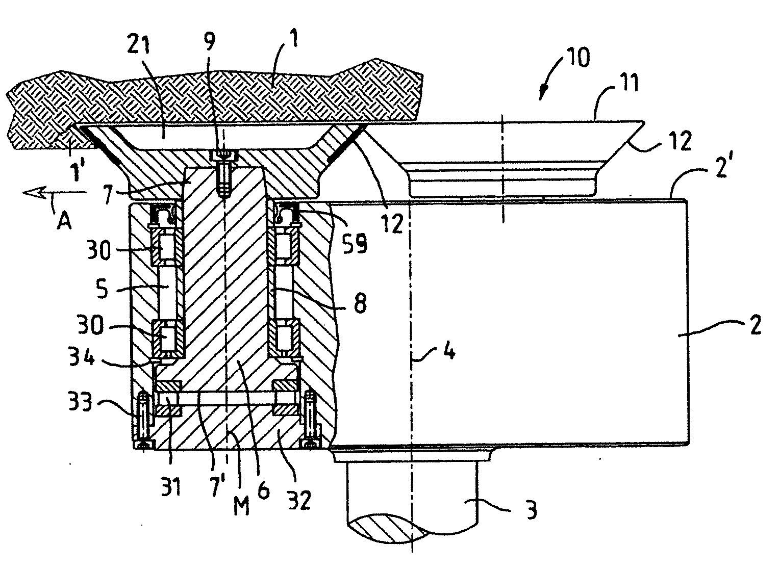
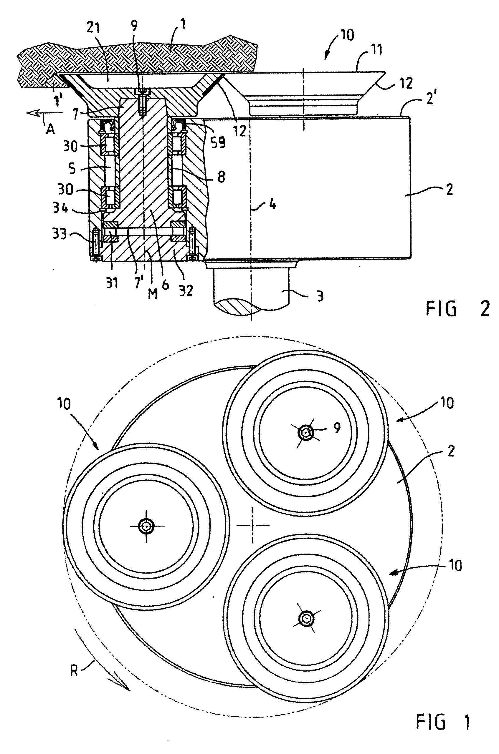
[0024]Referring now to the drawings wherein the showings are for the purpose of illustrating preferred and alternative embodiments of the invention only and not for the purpose of limiting same, FIGS. 1 and 2 show, of a machine (otherwise not shown in any more detail) for removing material such as rock at a schematically shown working face 1, a machine head 2 which rotates about the central axis 4 of the machine head 2 by means of the drive shaft 3. The machine head 2 can be mounted, for example via the drive shaft 3, on a tunneling machine, a heading machine, a selective-cut or full-thickness machine or a machine working with superimposed impact. In the exemplary embodiment shown, the machine head 2 has three shaft head receptacles 5, in each of which a tool shaft 6 is mounted. A roller drill designated overall by reference numeral 10 and working according to the undercutting principle is fastened in a rotationally fixed manner to the free end 7 of each tool shaft 6, said shaft end...


PUM


Abstract

A roller drill for removing material, such as in particular rock, minerals or the like, according to the undercutting principle, comprising a cutting face which is formed concentrically around a central axis and widens conically toward an end face of the roller drill, and includes a supporting body which is arranged on the inner side of the cutting face and extends up to the end face of the tool. In order to provide a roller drill or a roller bit of which the tool life or service life is improved compared with the prior art, the cutting face is made of a harder material than the supporting body and the supporting body forms an annular web which is conical at least at an outer circumferential wall and which defines with its inner circumferential wall a free space at the end face of the tool. The tool can resharpen itself automatically due to the free space and the dissimilar material combination.

Description

[0001]This application claims priority to and the benefit of the filing date of International Application No. PCT / EP2007 / 008120, filed Sep. 18, 2007, which application is incorporated by reference into the specification of this application.[0002]The invention relates to a roller drill or a roller bit for removing material, such as in particular rock, minerals or the like, according to the undercutting principle, comprising a cutting face which is formed concentrically around a central axis and widens conically toward the end face of the roller drill, and comprising a supporting body which is arranged on the inner side of the cutting face and extends up to the end face of the tool.BACKGROUND OF THE INVENTION[0003]Different types of cutting systems with which work can be carried out in the field of mining or of road construction by means of roller drills or roller bits according to the undercutting principle are known in the prior art. Roller drills or roller bits which work according...

Claims


Application Information

Patent Timeline
Patent Type & Authority Applications(United States)
IPC IPC(8): E21C25/18
CPCE21C27/32
Inventor BECHEM, ULRICHBECHEM, PHILIP
Owner CATERPILLER GLOBAL MINING EURO GMBH
Why Eureka
Try Eureka