
Motor drive circuit

a technology of motor drive and circuit, which is applied in the direction of motor/generator/converter stopper, dynamo-electric converter control, dc motor rotation control, etc., can solve the problem of higher cost of the motor drive circui

Active Publication Date: 2010-09-02
SEMICON COMPONENTS IND LLC
View PDF4 Cites 7 Cited by
  • Summary
  • Abstract
  • Description
  • Claims
  • Application Information

AI Technical Summary

Benefits of technology

The invention is a motor drive circuit that includes a first and second power supply lines and an H-bridge circuit. The circuit includes four transistors and corresponding diodes connected in series to form a half-bridge. The first and second power supply lines are connected to the input electrodes of the transistors, and a motor coil is connected between the output electrodes. The circuit also includes a control circuit that controls the H-bridge circuit to turn on and off the transistors in a complementary manner and to prevent the transistors from being turned on when the power supply voltage is too low. The technical effect of this invention is to provide a more efficient and reliable motor drive circuit that can operate at a wide range of power supply voltages.

Problems solved by technology

However, the method requires increasing a size of the Zener diode as a size of the motor increases, resulting in a higher cost of the motor drive circuit.

Method used


Image

  • Motor drive circuit
  • Motor drive circuit
  • Motor drive circuit

Examples


Embodiment Construction

[0017]A motor drive circuit according to an embodiment of this invention is hereafter described in detail.

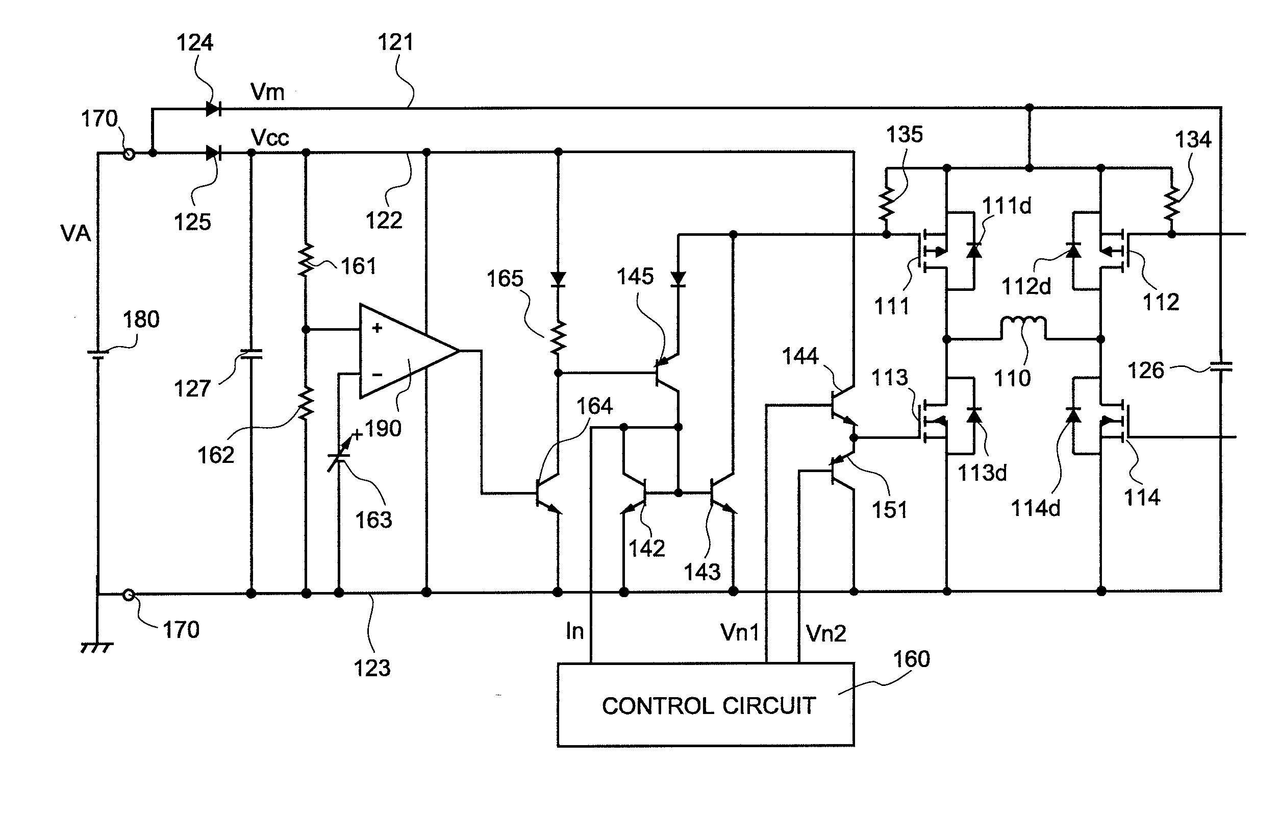
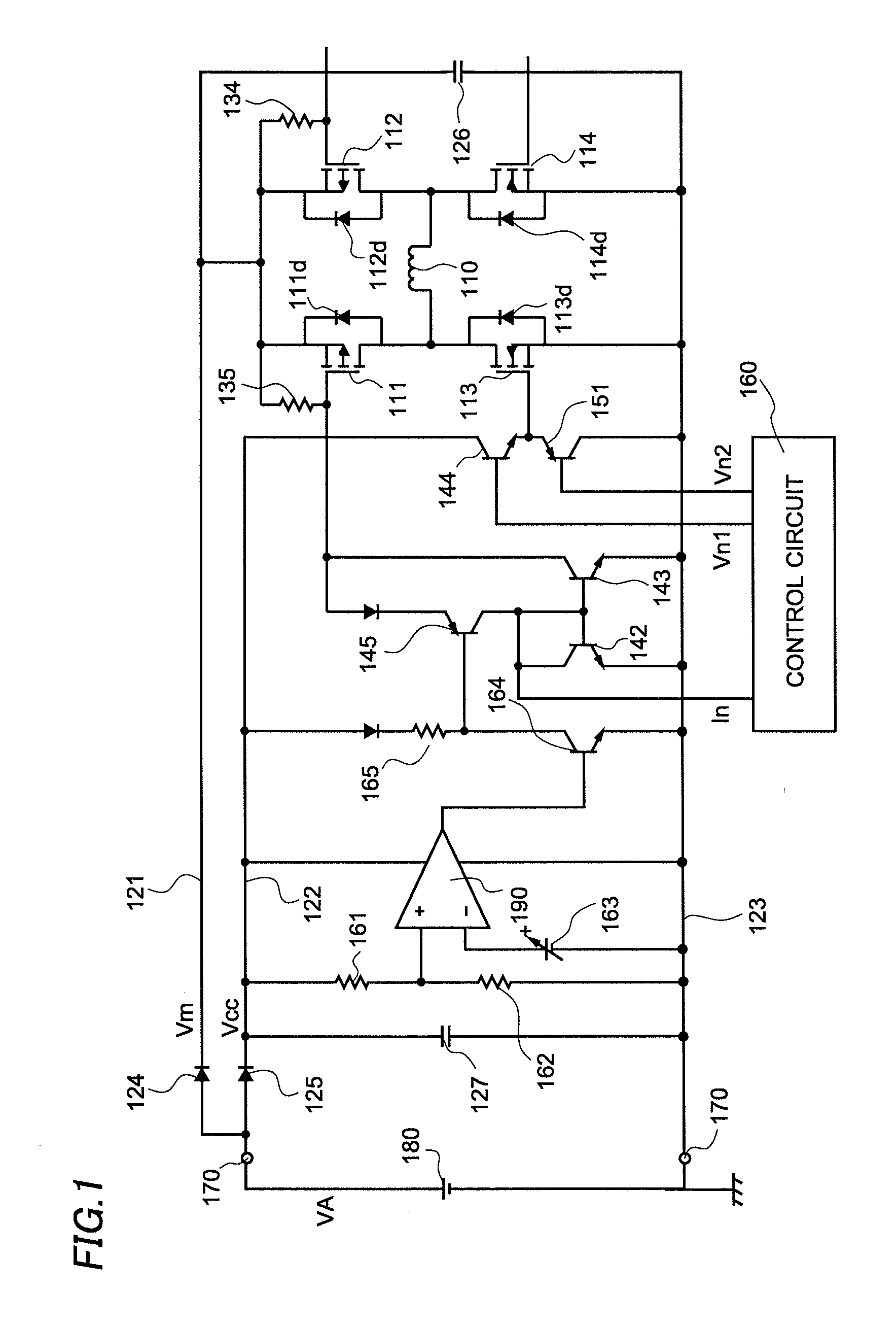
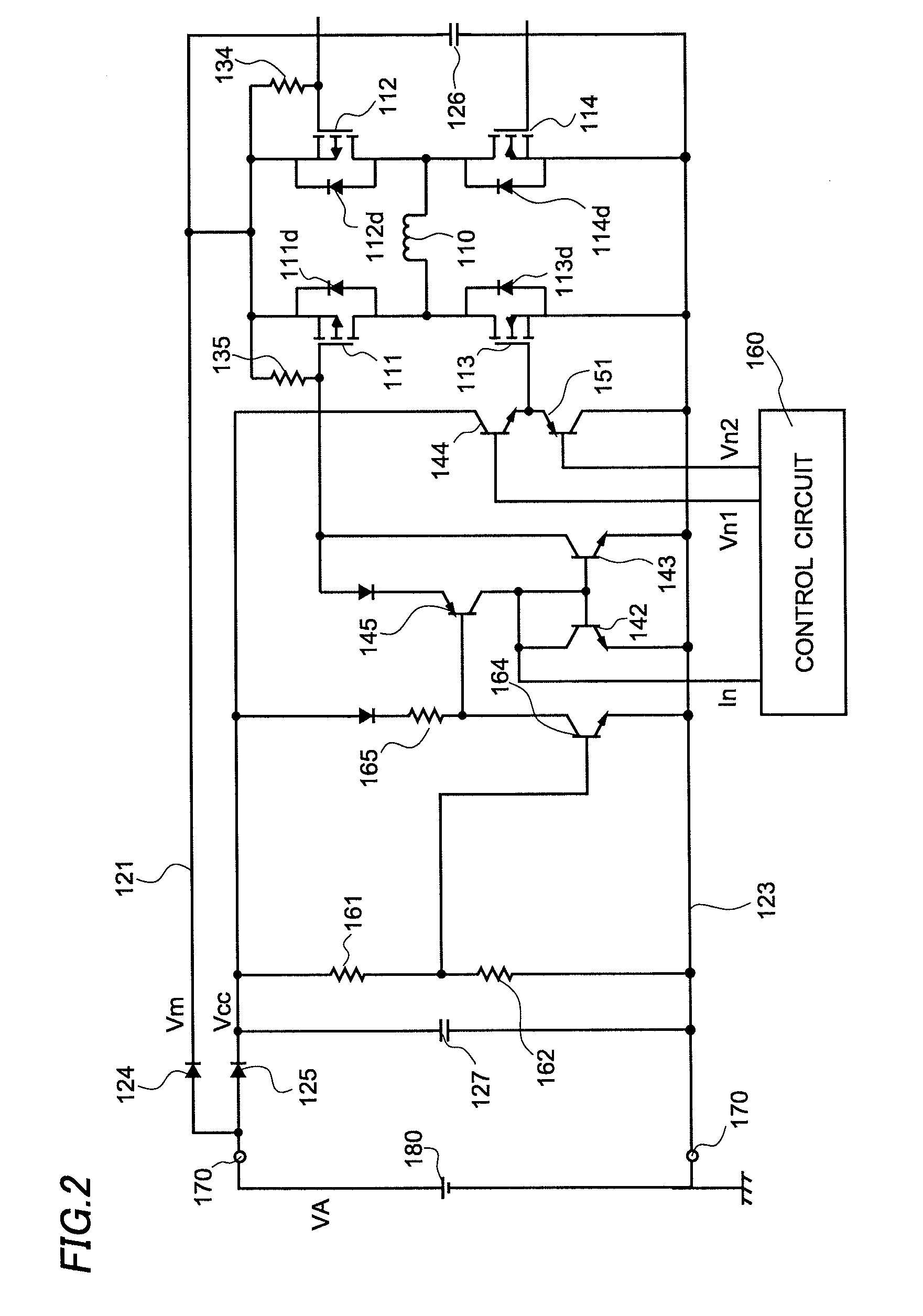
[0018]FIG. 1 shows an example of a structure of the motor drive circuit according to the embodiment of this invention. The motor drive circuit drives a single-phase motor such as a fan motor, for example, and controls an electric current flowing through a motor coil 110. The motor drive circuit is formed to include P-channel type MOSFETs 111 and 112, N-channel type

[0019]MOSFETs 113 and 114, power supply lines 121 and 122, a ground line 123, diodes 124 and 125, capacitors 126 and 127, NPN type transistors 142-144, and 164, PNP type transistors 145 and 151, a control circuit 160, a comparator 190, resistors 161, 162 and 135, a reference voltage source 163, and a connector 170.

[0020]First, the structure of the motor drive circuit according to the embodiment is described in detail.

[0021]The MOSFETs 111-114 constitute an H-bridge circuit. To describe the H-bridge circuit more in deta...


PUM


Abstract

This invention provides a motor drive circuit, which makes it possible to prevent braking when a power supply voltage is lower than a predetermined voltage while suppressing at a low cost a rise in a voltage on a power supply line when a kickback occurs. The motor drive circuit is formed to include first and second power supply lines connected with and shunted from a power supply, an H-bridge circuit, and a means to control the H-bridge circuit. The means controls the H-bridge circuit so that a regeneration path is not created in the H-bridge circuit when the power supply voltage is lower than a predetermined voltage.

Description

CROSS-REFERENCE OF THE INVENTION[0001]This application claims priority from Japanese Patent Application No. 2009-046353, the content of which is incorporated herein by reference in its entirety.BACKGROUND OF THE INVENTION[0002]1. Field of the Invention[0003]This invention relates to a motor drive circuit.[0004]2. Description of the Related Art[0005]When driving a motor with an H-bridge circuit, it is necessary to prevent MOSFETs from being destroyed by a rise in a voltage caused at an occurrence of a kickback.[0006]Japanese Patent Application Publication No. 2005-269885 discloses a method to suppress the rise in the voltage at the occurrence of the kickback using a Zener diode, for example. However, the method requires increasing a size of the Zener diode as a size of the motor increases, resulting in a higher cost of the motor drive circuit.[0007]On the other hand, Japanese Patent Application Publication No. 2007-259657 discloses a motor drive circuit that prevents the destruction ...

Claims


Application Information

Patent Timeline
Patent Type & Authority Applications(United States)
IPC IPC(8): H02P6/08H02P7/28
CPCH02P29/025H02P7/0044H02P7/04
Inventor NOIE, JOJI
Owner SEMICON COMPONENTS IND LLC
Learn More