Resonator element and oscillator

a technology of resonance element and oscillator, which is applied in the direction of oscillator, piezoelectric/electrostrictive/magnetostrictive device, semiconductor device, etc., can solve the problems of vibration energy loss, deterioration of resonance performance, etc., and achieves a longer relaxation time, lower relaxation frequency, and higher thermal conductivity

Inactive Publication Date: 2010-09-02
SEIKO EPSON CORP
View PDF7 Cites 11 Cited by
  • Summary
  • Abstract
  • Description
  • Claims
  • Application Information

AI Technical Summary

Benefits of technology

[0011]An advantage of the invention is to provide a resonator element that can prevent the lowering of a Q value due to thermal conduction, and an oscillator in which the resonator element is mounted.
[0012]The present invention is intended to solve at least part of the mentioned problems and can be implemented by the following aspects of the invention.
[0013]According to a first aspect of the invention, a resonator element includes a resonating body having a first region and a second region, the first region receiving a compression stress or an extension stress by a vibration, the second region receiving an extension stress responding to the compression stress in the first region, or a compression stress responding to the extension stress of the first region; and at least one film layer, on a surface of the resonating body between the first and the second regions, having thermal conductivity higher than thermal conductivity of the resonating body. The film layer includes a recessed section in which at least one film layer is removed between the first and the second regions.
[0014]In the resonator element, a part of the film formed on the surface of the resonating body is removed between the first and the second regions both of which alternately receive the compression stress and the extension stress when the resonator element vibrates. The heat transfer path between the compression region and the extension region is, thus, restricted, lengthening the relaxation time. As a result, the relaxation frequency is lowered. This lowering of the relaxation frequency enables the lowering of the Q value due to the thermal conduction to be prevented, attaining a high Q value.
[0015]The resonating body may include a groove section having the recessed section.
[0016]The formation of the groove section lengthens the relaxation time, which is a period during which the temperatures of the compression region and the extension region come to an equilibrium state. As a result, the relaxation frequency is lowered. This lowering of the relaxation frequency enables the lowering of the Q value due to the thermal conduction to be prevented, attaining a high Q value.

Problems solved by technology

Vibration energy losses generated in the flexural vibration of the tuning fork type resonator element cause a resonator to deteriorate the performances.
The thermal conduction generated between the compression portions receiving the compression stress and the extension portions receiving the extension stress of the resonating arms that vibrate in a flexural mode causes the vibration energy losses.

Method used


Image

  • Resonator element and oscillator
  • Resonator element and oscillator
  • Resonator element and oscillator

Examples


first embodiment

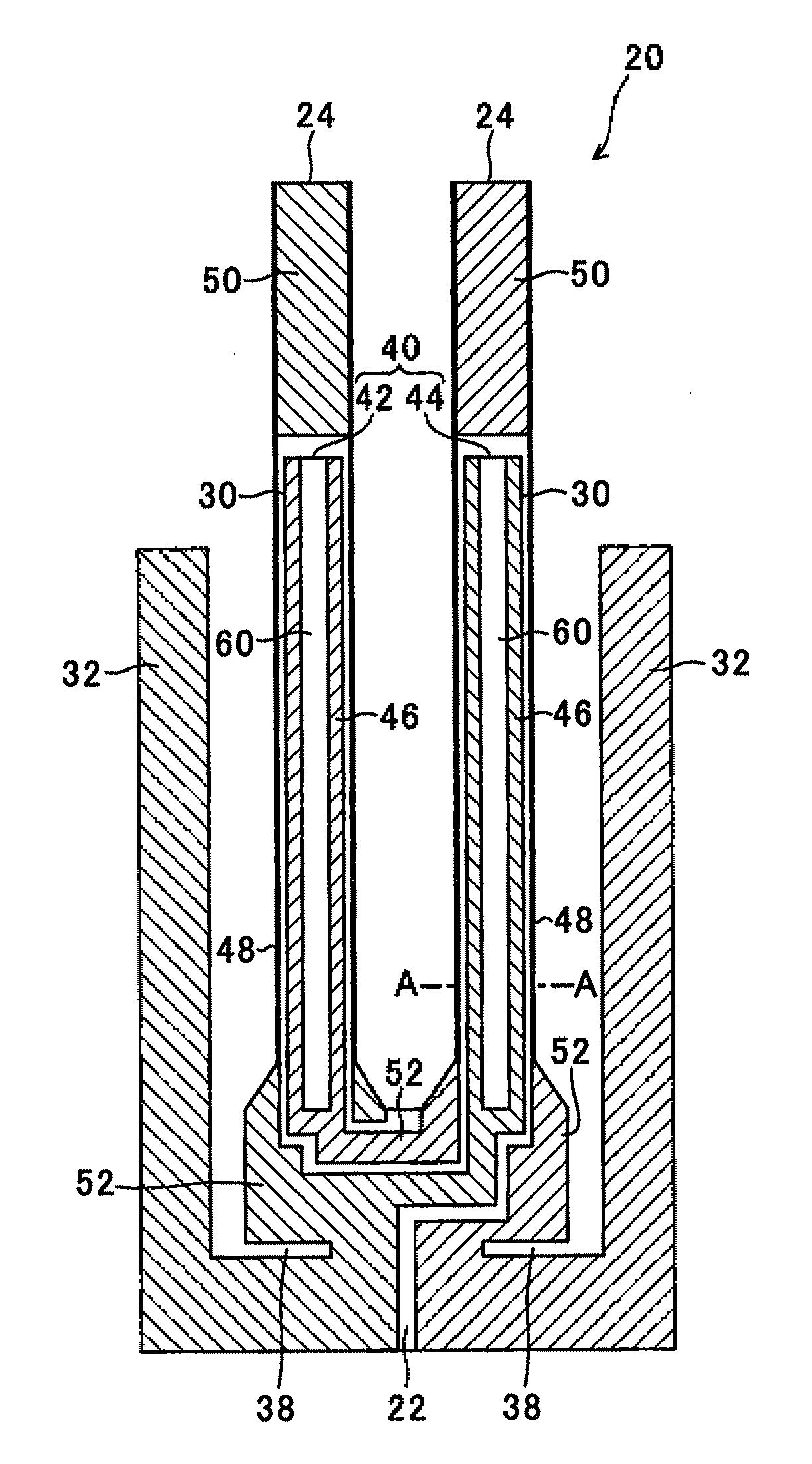
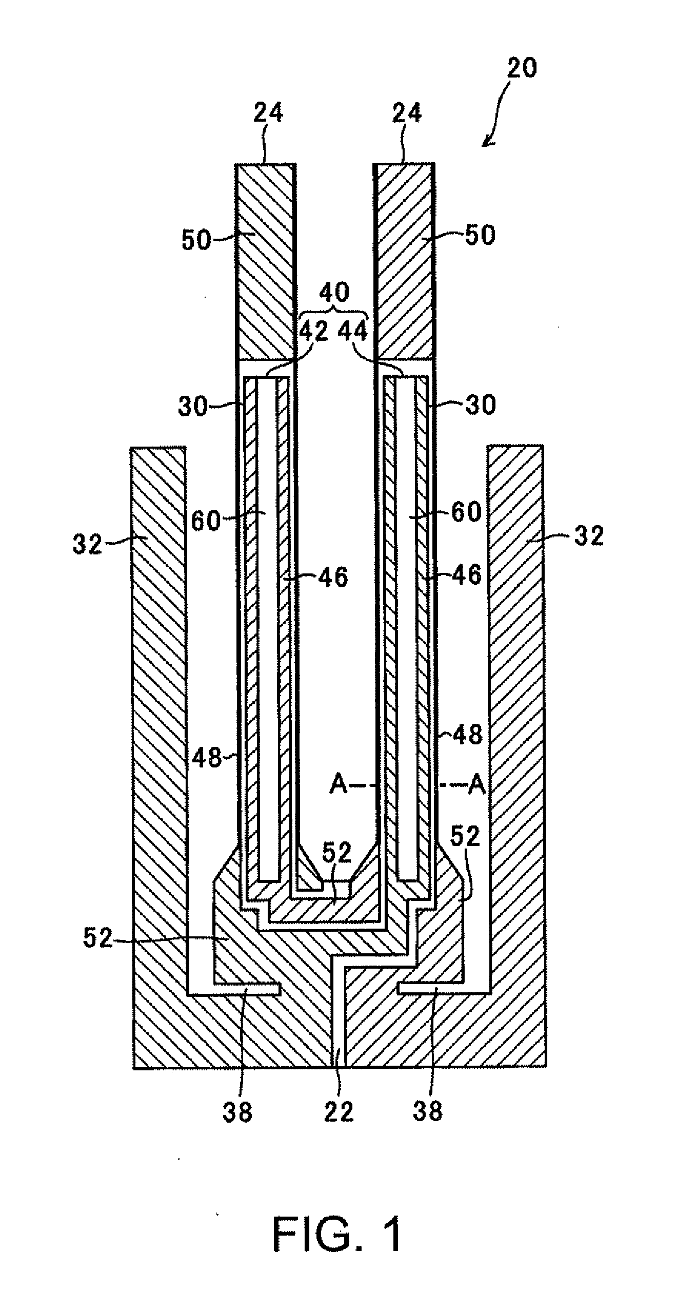
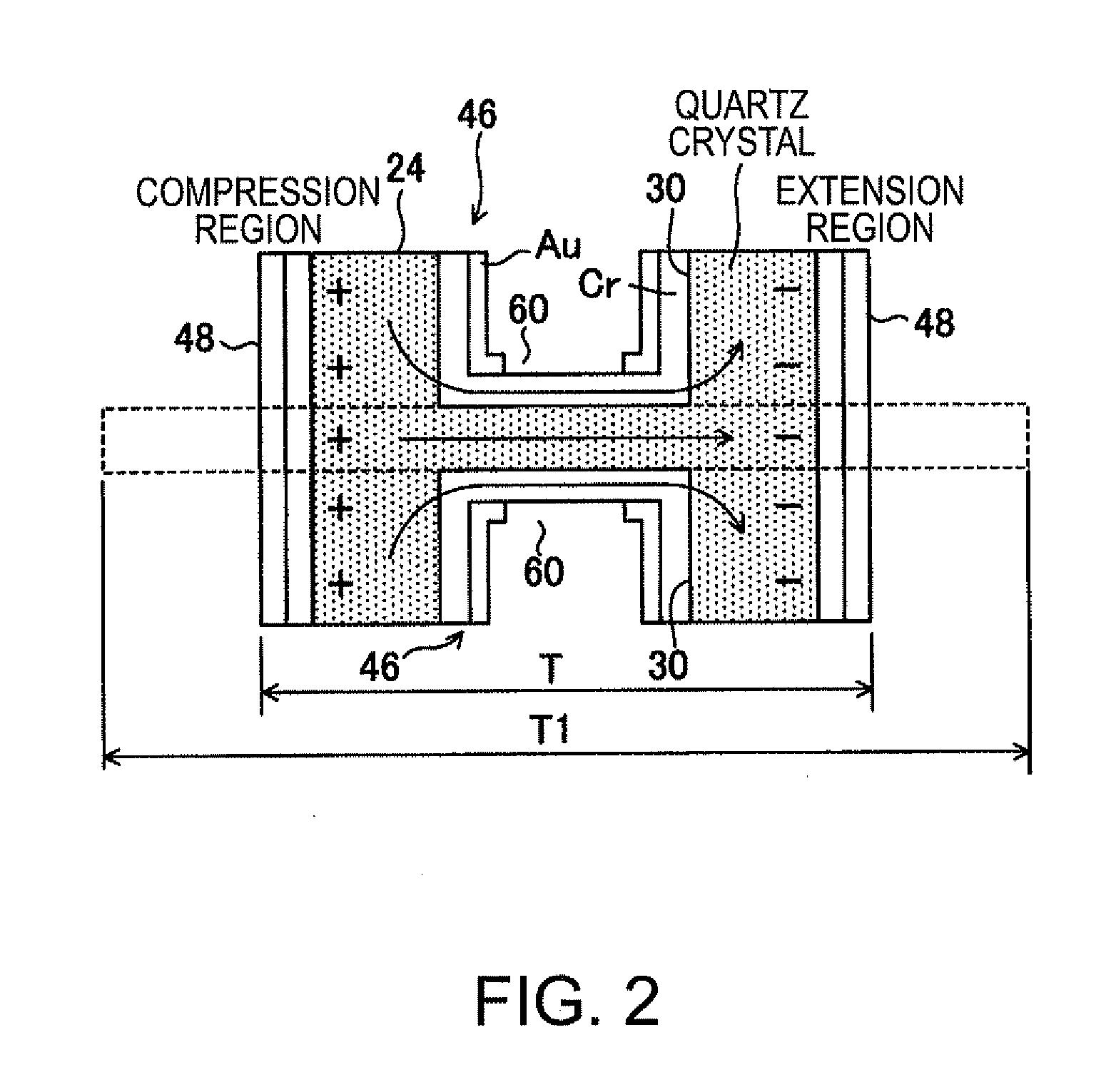
[0033]A resonator element and an oscillator of the invention are described below in detail with reference to the accompanying drawings. In the following embodiments, a tuning fork type piezoelectric resonator element is described as an example of the resonator element. The resonator element of the invention, however, is not limited to the tuning fork type piezoelectric resonator element. The invention can be applied to any resonator elements as long as they produce temperature increasing portions and temperature decreasing portions so as to be responded to each other when they are vibrated. The resonator element is not limited to a piezoelectric body. The vibration mode is also not limited to a flexural vibration mode. FIG. 1 is a schematic view illustrating a structure of a resonator element of the invention. FIG. 2 is a cross sectional view taken along the line A-A of FIG. 1.

[0034]A resonator element 20 includes a base section 22, a pair of resonating arms 24 extending from the ba...

second embodiment

[0052]In the resonator element of the second embodiment, the recessed section is provided to the film having thermal conductivity higher than that of the material of the resonating body so as to cut off the heat transfer path between the compression region and the extension region in the film. As a result, only the long groove 30 functions as the heat transfer path. Likewise the resonator element shown in FIGS. 1 and 2, this structure causes the relaxation time to lengthen, lowering the relaxation frequency. As a result, a high Q value can be attained.

[0053]FIG. 4 is a plan view illustrating a featured part of a resonator element according to a third embodiment of the invention. As shown in FIG. 4, the resonating arm 24 of the third embodiment is structurally different from that of the first embodiment in that the first exciting electrode 46 formed inside the long groove 30 has an end section 62 in which the recessed section is not formed. Other structure is the same as that of the ...

third embodiment

[0054]In the resonator element of the third embodiment, the first exciting electrode 46 is formed on the bottom surface, which corresponds to the end section 62, of the long groove 30 of the resonating arm 24, and the recessed section 60 is formed on the bottom surface, excluding the end section 62 and a root section 61, of the long groove 30. In a plan view of the long groove 30, the recessed section 60 is surrounded by the end section 62 and the root section 61.

[0055]The recessed section 60a of the second embodiment can be applied to the resonating arms of the third embodiment.

[0056]The resonator element of the third embodiment can lengthen the relaxation time since the recessed sections 60 are provided to the resonating arms 24. Further, the recessed section 60 is not formed, but the electrode is formed at the end section of the long groove 30. This structure can reduce ohmic losses (resistance losses) with assured electric conduction.

[0057]FIGS. 5A and 5B are cross sectional vie...


PUM

PropertyMeasurementUnit
compression stressaaaaaaaaaa
extension stressaaaaaaaaaa
thermal conductivityaaaaaaaaaa

Abstract

A resonator element includes: a resonating body having a first region and a second region, the first region receiving a compression stress or an extension stress by a vibration, the second region receiving an extension stress responding to the compression stress in the first region, or a compression stress responding to the extension stress of the first region; and at least one film layer, on a surface of the resonating body between the first and the second regions, having thermal conductivity higher than thermal conductivity of the resonating body. In the element, the film layer includes a recessed section in which at least one film layer is removed between the first and the second regions.

Description

BACKGROUND[0001]1. Technical Field[0002]The present invention relates to prevent a lowering of Q value due to thermal conduction, particularly of a resonator element and an oscillator.[0003]2. Related Art[0004]Tuning fork type piezoelectric resonator elements have been widely used. In such tuning fork type piezoelectric resonator element, a pair of resonating arms vibrates to be closer to each other and apart from each other. Vibration energy losses generated in the flexural vibration of the tuning fork type resonator element cause a resonator to deteriorate the performances. For example, an increase of a CI (crystal impedance) value or a decrease of a Q value occurs. Thermal conduction is considered as one factor of the vibration energy losses.[0005]FIG. 7 is an explanatory view of the thermal conduction of a piezoelectric resonator element. As shown in FIG. 7, a piezoelectric resonator element 1 includes two resonating arms 3 and 4 extending from a connecting section 2 in parallel...

Claims


Application Information

Patent Timeline
Patent Type & Authority Applications(United States)
IPC IPC(8): H03B5/30
CPCH03H9/0547H03H9/215H03H9/1021H01L2224/48091H01L2924/16195H01L2924/00014
Inventor YAMADA, AKINORI
Owner SEIKO EPSON CORP
Why Eureka
Try Eureka