Liquid crystal display device

a liquid crystal display and display device technology, applied in the field of liquid crystal display devices, can solve the problems of difficult gradual reduction of luminance, low luminance of planar beam of light emitted from the conventional light guide plate type backlight unit, and often occurring motion blur, so as to achieve the effect of reducing luminance and facilitating two-dimensional control

Active Publication Date: 2010-09-02
PANASONIC LIQUID CRYSTAL DISPLAY CO LTD +1
View PDF5 Cites 122 Cited by
  • Summary
  • Abstract
  • Description
  • Claims
  • Application Information

AI Technical Summary

Benefits of technology

[0017]One object of the present invention is to provide a technique that enables a liquid crystal display device including a light guide plate type backlight unit to control a surface luminance of a planar beam of light for irradiating its liquid crystal display panel so as to decrease the luminance concentrically from the center toward the perimeter.
[0018]One object of the present invention is to provide a technique that facilitates two-dimensional control of a surface luminance of a planar beam of light for irradiating a liquid crystal display panel in a liquid crystal display device including a light guide plate type backlight unit.
[0032]The liquid crystal display device according to the present invention is capable of controlling the surface luminance of the planar beam of light radiated from the light guide plate type backlight unit onto the liquid crystal display panel so as to decrease the luminance concentrically from the center toward the perimeter.
[0033]The liquid crystal display device according to the present invention can also perform two-dimensional control more easily than in the prior art on the surface luminance of the planar beam of light radiated from the light guide plate type backlight unit onto the liquid crystal display panel.

Problems solved by technology

Consequently, when a light guide plate type backlight unit is used in a liquid crystal display device that has “hold type” light emission characteristics, a motion blur often occurs due to the luminance response characteristics of respective pixels.
However, as mentioned above, a planar beam of light emitted from the conventional light guide plate type backlight unit tends to become lower in luminance as the distance increases from the light incidence side surface of the light guide plate.
Realizing an even surface luminance of a planar beam of light is relatively easy in the conventional light guide plate type backlight units, but it is difficult to decrease the luminance gradually and concentrically from the center toward the perimeter.
This makes it difficult for liquid crystal display devices that include the conventional light guide plate type backlight unit to switch between setting the surface luminance of the planar beam of light even for one circumstance and varying the surface luminance of the planar beam of light two-dimensionally for another circumstance.
Another problem is that dynamically performing two-dimensional control of the surface luminance as in, for example, the area-based control is difficult in liquid crystal display devices that include the conventional light guide plate type backlight unit.

Method used


Image

  • Liquid crystal display device
  • Liquid crystal display device
  • Liquid crystal display device

Examples


first embodiment

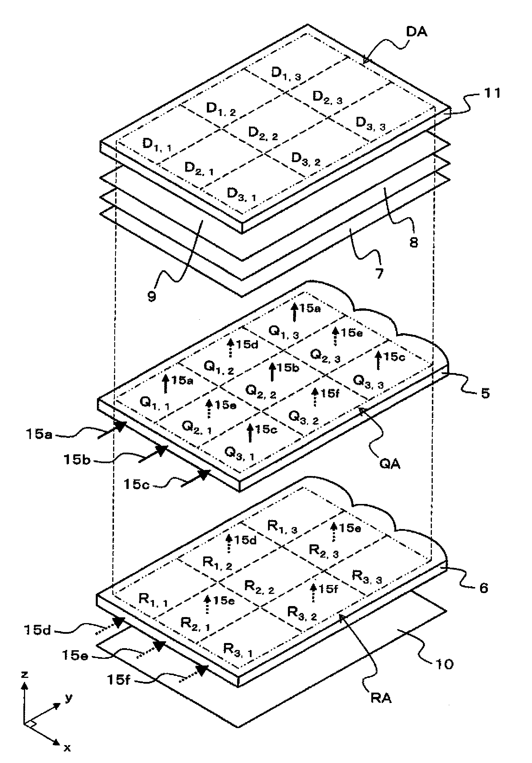
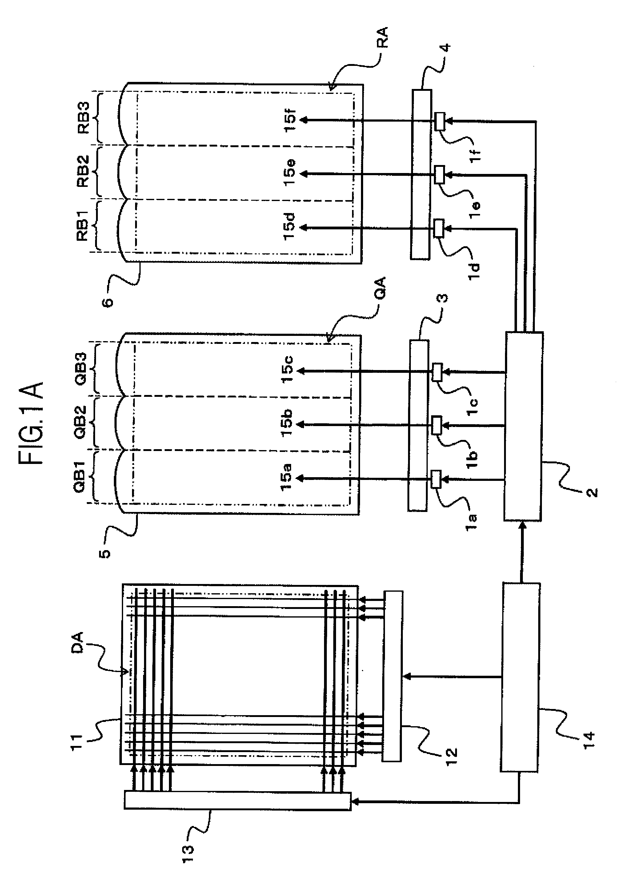
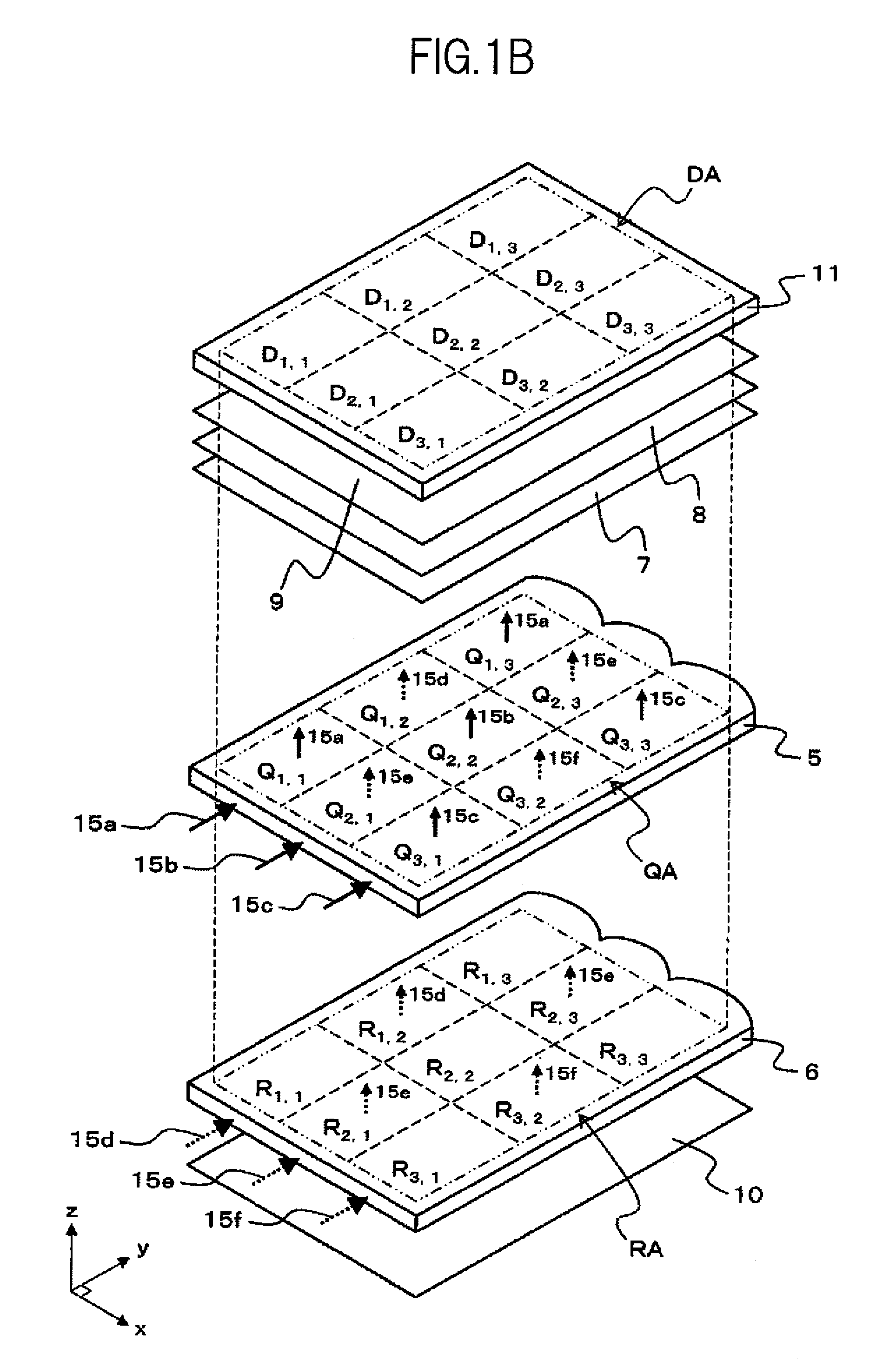
[0076]FIGS. 1A and 1B are schematic diagrams illustrating a schematic structure and operation principle of a liquid crystal display device according to a first embodiment of the present invention.

[0077]FIG. 1A is a schematic block diagram illustrating an example of the schematic structure of the liquid crystal display device according to the first embodiment. FIG. 1B is a schematic perspective view supplementing the illustration of the schematic structure of FIG. 1A.

[0078]The liquid crystal display device of the first embodiment is a liquid crystal display device that has a light guide plate type (also called edge light type) backlight unit, and includes, for example, as illustrated in FIGS. 1A and 1B, light source units 1a, 1b, 1c, 1d, 1e, and 1f, a light source control circuit 2, a first lens waveguide 3, a second lens waveguide 4, a first light guide plate 5, a second light guide plate 6, a light diffusing sheet 7, a prism sheet 8, a prism sheet with light diffusing function 9, a...

second embodiment

[0168]FIGS. 7A and 7B are schematic diagrams illustrating the schematic structure of a main part of a liquid crystal display device according to a second embodiment of the present invention.

[0169]FIG. 7A is a schematic plan view illustrating an example of the schematic structures of a first light source unit group, a first lens waveguide, and a first light guide plate. FIG. 7B is a schematic plan view illustrating an example of the schematic structures of a second light source unit group, a second lens waveguide, and a second light guide plate in the liquid crystal display device of the second embodiment.

[0170]The liquid crystal display device of the second embodiment is basically the same as the liquid crystal display device of the first embodiment, and structured as illustrated in FIGS. 1A and 1B. Accordingly, only differences from the first embodiment are described in the second embodiment.

[0171]First, the liquid crystal display device of the second embodiment differs from the li...

third embodiment

[0186]FIGS. 8A to 8D are schematic diagrams illustrating the schematic structure and operation principle of a main part of a liquid crystal display device according to a third embodiment of the present invention.

[0187]FIG. 8A is a schematic perspective view illustrating an example of the schematic structure of the main part of the liquid crystal display device according to the third embodiment. FIG. 8B is a schematic plan view illustrating an example of the schematic structures of a first light guide plate, a first light source unit group, and a first lens waveguide. FIG. 8C is a schematic plan view illustrating an example of the schematic structures of a second light guide plate, a second light source unit group, and a second lens waveguide. FIG. 8D is a schematic plan view illustrating an example of the schematic structures of a third light guide plate, a third light source unit group, and a third lens waveguide.

[0188]The liquid crystal display devices of the first embodiment and ...


PUM

PropertyMeasurementUnit
surface angleaaaaaaaaaa
areasaaaaaaaaaa
area DAaaaaaaaaaa

Abstract

A liquid crystal display device includes a liquid crystal display panel, a plurality of groups of light source units, a plurality of light guide plates, and a light source control circuit configured to control light amounts of the light source units. The plurality of light guide plates are configured to transmit light from the plurality of groups of the light source units. In each of the plurality of light guide plates, areas from which the transmitted light exiting toward the liquid crystal display panel differ from one another. One of the plurality of groups of the light source units paired with one of the plurality of light guide plates includes at least two light source units that are controlled in light amount independently. A number of the areas of the one of the plurality of light guide plates is at least a number of the light source units thereof.

Description

CROSS-REFERENCE TO RELATED APPLICATION[0001]The present application claims priority from Japanese Application JP2009-047855 filed on Mar. 2, 2009, the content to which is hereby incorporated by reference into this application.BACKGROUND OF THE INVENTION[0002]1. Field of the Invention[0003]The present invention relates to a liquid crystal display device, and more particularly to a technique effective when applied to a liquid crystal display device that includes a light guide plate type backlight unit.[0004]2. Description of the Related Art[0005]Conventional liquid crystal display devices include ones that use a light guide plate type backlight unit. In the light guide plate type backlight units, a light guide plate is disposed in, for example, a place that overlaps with the display area of a liquid crystal display panel, and a light source such as a light emitting diode or a fluorescent light is placed at an end of the light guide plate. Compared to direct lit backlight units having ...

Claims


Application Information

Patent Timeline
Patent Type & Authority Applications(United States)
IPC IPC(8): G02F1/13357
CPCG02B6/003G02B6/0038G02B6/0068G02B6/0073G09G2320/0233G02B6/0083G02F1/133615G02F2001/133601G09G3/342G02B6/0076G02F1/133601
Inventor SUGITA, TATSUYAADACHI, MASAYAOKA, SHINICHIRO
Owner PANASONIC LIQUID CRYSTAL DISPLAY CO LTD
Why Eureka
Try Eureka