Client/Bridge and Method and System for Using Same

a client and bridge technology, applied in the field of client/bridge and method and, can solve the problems of reducing the efficiency of the system, slowed down, and increasing the cost of the overall network, so as to facilitate layer 2 bridging, facilitate synchronization and maintenance of layer 2 forwarding fabric consistency, and facilitate communication

Active Publication Date: 2010-09-02
SIEMENS CANADA LTD
View PDF8 Cites 13 Cited by
  • Summary
  • Abstract
  • Description
  • Claims
  • Application Information

AI Technical Summary

Benefits of technology

[0012]One advantage of the present invention is to facilitate Layer 2 bridging within a mixed wired and wireless network, and in a preferred embodiment a wireless network based on the IEEE 802.11 infrastructure where there are IEDs connected to a Client/Bridge through a wired interface. In one aspect, the present invention facilitates synchronization and maintenance of Layer 2 forwarding fabric consistency within the overall network topology across both wired and wireless boundaries.
[0013]In another aspect, an advantage of the present invention relates to acquiring information regarding wired devices located behind the Client/Bridge in a seamless manner. In one preferred embodiment this is accomplished by the Client/Bridge monitoring communication between the wired devices behind the Client/Bridge and the Access Point. This information obtained by the Client/Bridge, which may be referred to as context cache information, is then mirrored in the associated AP communicating with the Client/Bridge to facilitate communication between other devices in the network and the wired devices, which could be any Intelligent Electrical Device (IED), connected behind the Client/Bridge. This also facilitates recovery of the Client/Bridge in the case of temporary failure, such as loss of power, by permitting this information regarding the IEDs connected to the Client/Bridge to be resent to the Client/Bridge from the AP at resumption of operation of the Client/Bridge. In this way, the AP acts as a remote backup for this information, improving recovery of the network in the event of a temporary loss of a Client/Bridge.
[0014]In this embodiment, the Access Point also allows for the use of an alternate 4A mode frame format (not in standard usage) which defines 4 address fields and is supported by the IEEE 802.11 infrastructu

Problems solved by technology

While useful the standard IEEE 802.11 infrastructure (which relies entirely on 3A mode frame transactions) suffers from the disadvantage that each wireless Client can only represent a single IED, such that a number of separate clients all with wireless capabilities, are required in order to communicate with the Access Point (AP) and therefore the other IEDs in the network.
This can increase the cost of the overall network by requiring a large number of wireless clients.
Furthermore, a large number of wireless cl

Method used


Image

  • Client/Bridge and Method and System for Using Same
  • Client/Bridge and Method and System for Using Same
  • Client/Bridge and Method and System for Using Same

Examples


Embodiment Construction

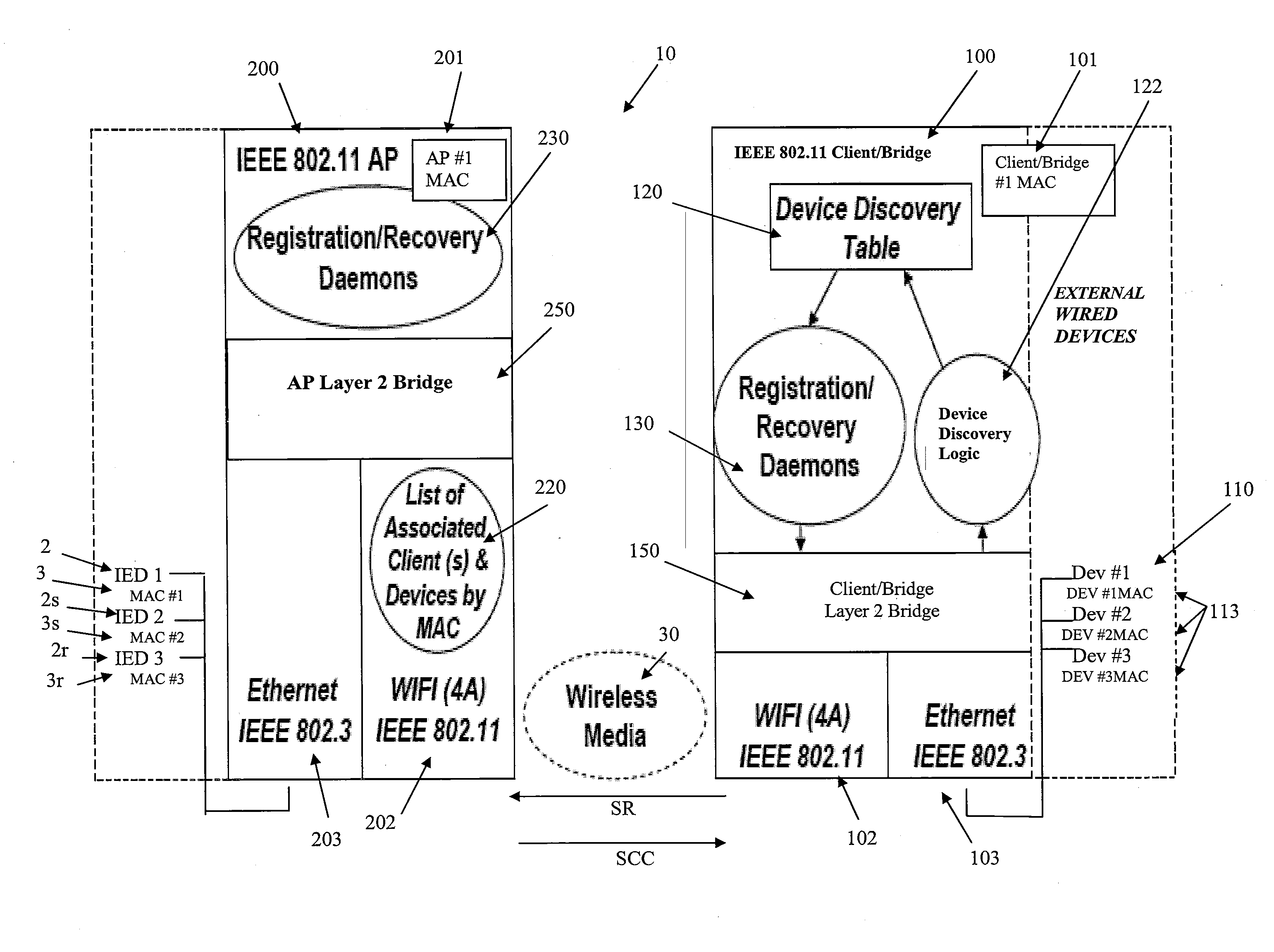
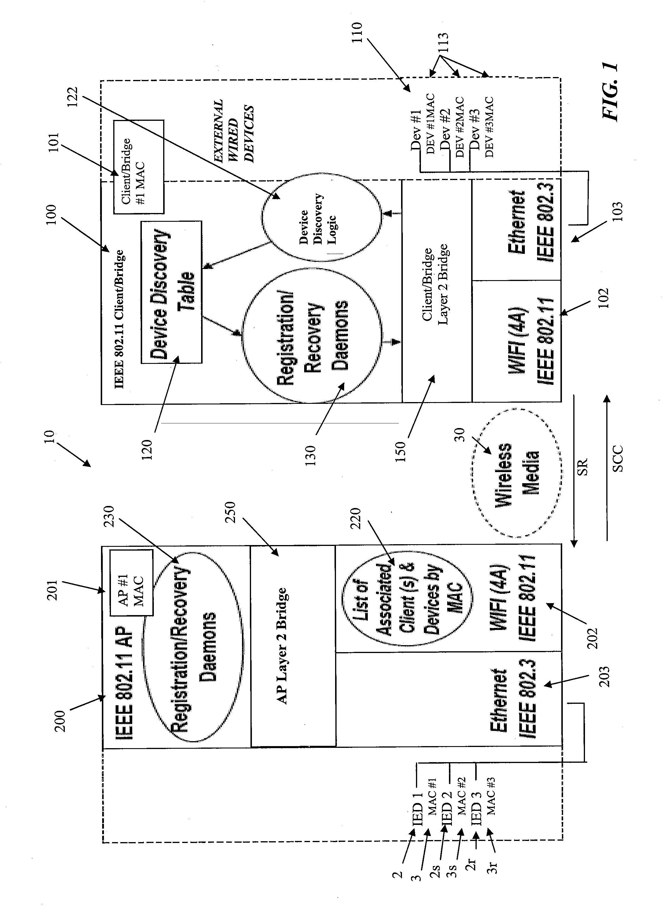
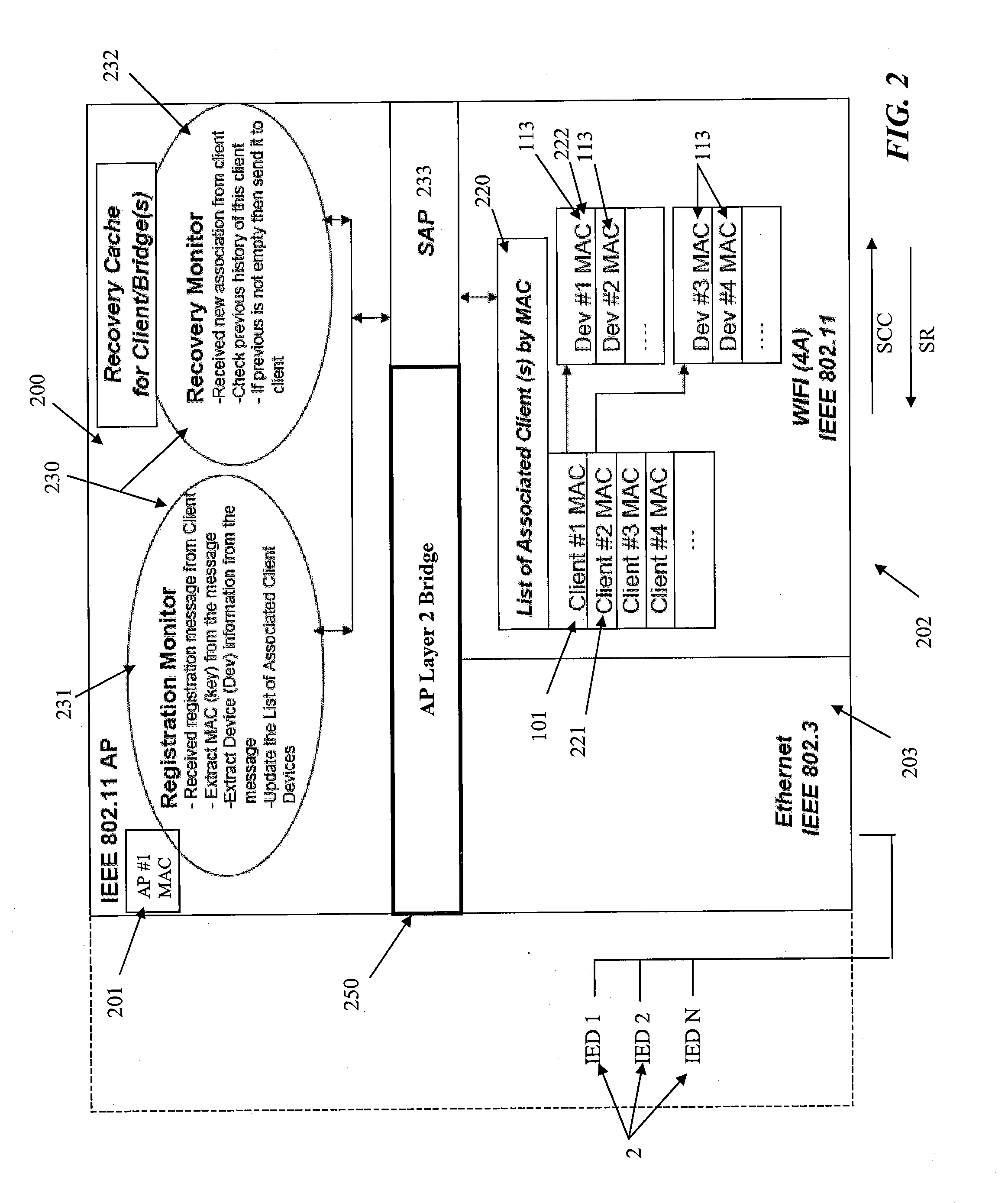
[0028]The present invention enables the implementation of Layer 2 bridging within IEEE 802.11 infrastructure Point-to-Point (P2P) and Point-to-Multipoint (P2MP) network topologies by utilizing the 4 address modes of a wireless interface, such as the IEEE 802.11 infrastructure, while keeping the Layer 2 information synchronized and simultaneously maintaining the Layer 2 forwarding fabric consistency within the overall network topology including wired and wireless components of the network. As a result, the IEEE 802.11 infrastructure mode forms a 2-hop instead of a single-hop Layer 2 wireless carrier network permitting Intelligent Electronic Devices (IEDs) in the network to address two or more IEDs connected behind a Client / Bridge device through a wired connection. Wired End-Point (terminal) devices, such as IEDs including Remote Terminal Units (RTUs) or Personal Computers (PCs) which are directly or indirectly connected to either the Client / Bridge or the AP side of this IEEE 802.11 w...


PUM


Abstract

The transmission of data is accomplished across a network having wireless and wired interfaces. Data is transferred through a wireless interface from an Access Point to a Client/Bridge and then to one of a Intelligent Electrical Device (IED) connected to the Client/Bridge through a wired connection. Data is transferred from the Access Point to the Client/Bridge through a 4 address mode wireless interface having originator, transmitter, receiver and destination address fields. The originator address uniquely identifies an IED in the overall network, the transmitter address identifies the AP transmitting the data, the receiver address identifies the Client/Bridge receiving the data through the wireless interface while the destination address refers to one of the IEDs connected to the Client/Bridge through the wired interface. Communication can also be performed in reverse from one of the IEDs connected to the Client/Bridge through the wired interface to an IED in the overall network. The Client/Bridge determines context cache information representing the media access control numbers of each of the IEDs connected to the Client/Bridge through the wired interface and transfers this context cache information to the AP. In the event of a failure of the Client/Bridge, the context cache information stored at the AP can be transferred to the Client/Bridge using the wireless interface to facilitate recovery of the Client/Bridge.

Description

FIELD OF THE INVENTION[0001]This invention relates to a Client / Bridge, and method and system for using a Client / Bridge to provide Layer 2 bridging to transfer data in a mixed wired and wireless network. More specifically, the present invention relates to a method to provide Layer 2 bridging between an IEEE 802.11 compatible infrastructure and a wired infrastructure for point to point (P2P) and point to multipoint (P2MP) network topologies.BACKGROUND OF THE INVENTION[0002]In the past, mixed wireless and wired networks have been used to transfer data. One common standard for a wireless network is the standard IEEE 802.11 infrastructure network. In standard use, the IEEE 802.11 infrastructure network provides for a single hop transmission between an Access Point (AP) and a Client through a wireless medium, using a ‘3 address field’ format called the 3A mode frame.[0003]The IEEE 802.11 network will transfer data nominally using a 3A mode frame format which defines 3 address fields for s...

Claims


Application Information

Patent Timeline
IPC IPC(8): H04W40/00
CPCH04L12/4625H04L29/12839H04W84/22H04W8/26H04L61/6022H04L2101/622
Inventor LEVY, PHILABDUL, AMIN
Owner SIEMENS CANADA LTD
Why Eureka
Try Eureka