Supercharge Your Innovation With Domain-Expert AI Agents!

Video Encoding Method and Decoding Method, Apparatuses Therefor, Programs Therefor, and Storage Media for Storing the Programs

a multi-viewpoint video and encoding technology, applied in the field of encoding and decoding techniques of multi-viewpoint video images, can solve the problems of increasing the amount of code assigned to the relevant prediction residual, increasing the amount of code of parallax data, and the inability to achieve high total encoding efficiency, so as to improve the total encoding efficiency and reduce the amount of code of parallax displacement data

Active Publication Date: 2010-09-02
NIPPON TELEGRAPH & TELEPHONE CORP +1
View PDF4 Cites 19 Cited by
  • Summary
  • Abstract
  • Description
  • Claims
  • Application Information

AI Technical Summary

Benefits of technology

[0024]In order to solve the above problem, an object of the present invention is to decrease the amount of code of parallax data without making a considerable sacrifice of the accuracy of parallax compensation.
[0027]Generally, parallax displacement has a spatial correlation in an image frame. Therefore, when appropriate area division is set, and parallax displacement is encoded for each divided area, then the amount of code of parallax data can be reduced without degrading the prediction efficiency of parallax compensation.
[0031]A second mode of the video encoding and decoding methods of the present invention is basically similar to the above-described first mode. However, in the second mode, area division is performed so as to generate rectangular blocks. More specifically, rectangular block division (refer to FIG. 10 explained later) is defined for each macroblock. Data for such block division can be efficiently encoded by using a known entropy encoding technique (e.g., entropy encoding in H.264).
[0033]In accordance with the present invention, in video encoding and decoding methods for estimating parallax by using reference images, spatial correlation of parallax displacement data is used, so that the amount of code of parallax displacement data can be reduced without degrading the prediction efficiency in parallax compensation, thereby improving the total encoding efficiency.

Problems solved by technology

However, reference parallax, which is estimated on the decoding side, is not an optimum one in consideration of the prediction efficiency, and the amount of code assigned to the relevant prediction residual may be increased.
However, in such a technique which can be easily anticipated, as the parallax displacement is encoded for each pixel, the amount of code of parallax data increases, so that the total encoding efficiency cannot be high.

Method used


Image

  • Video Encoding Method and Decoding Method, Apparatuses Therefor, Programs Therefor, and Storage Media for Storing the Programs
  • Video Encoding Method and Decoding Method, Apparatuses Therefor, Programs Therefor, and Storage Media for Storing the Programs
  • Video Encoding Method and Decoding Method, Apparatuses Therefor, Programs Therefor, and Storage Media for Storing the Programs

Examples


Embodiment Construction

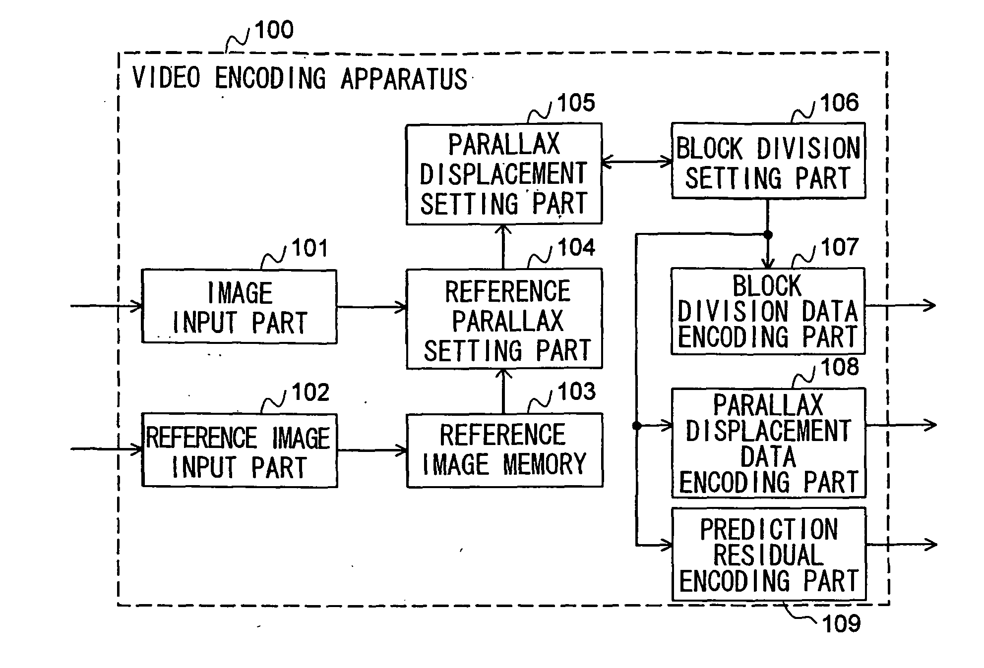
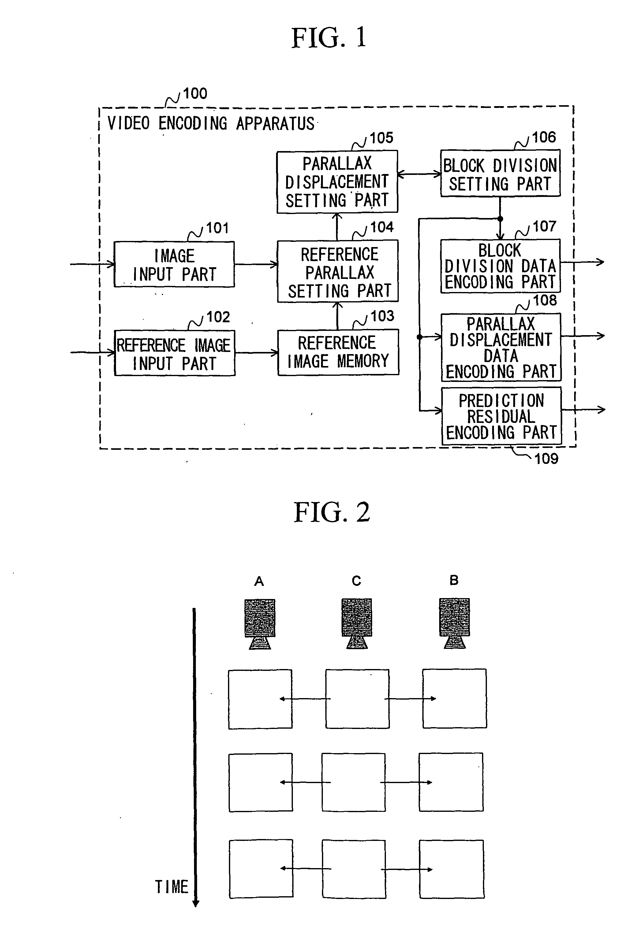
[0046]FIG. 1 is a diagram showing the structure of a video encoding apparatus as a embodiment of the present invention.

[0047]The video encoding apparatus 100 includes an image input part 101 into which each original image of camera C (i.e., target image to be encoded) is input; a reference image input part 102 into which decoded images (as reference images) of cameras A and B are input; a reference image memory 103 for storing each reference image; a reference parallax setting part 104 for obtaining reference parallax by using reference images; a parallax displacement setting part 105 for obtaining parallax displacement; a block division setting part 106 for setting a block division state; a block division data encoding part 107 for encoding block division data; a parallax displacement data encoding part 108 for encoding parallax displacement data; and a prediction residual encoding part 109 for encoding the relevant prediction residual.

[0048]FIG. 2 is a diagram showing reference re...


PUM


Abstract

By using parallax compensation which performs prediction by using parallax between video images, the video images are encoded as a single video image. Reference parallax for a target image to be encoded is set, wherein the reference parallax is estimated using a reference image; area division in an image frame is set; parallax displacement for each divided area is set, wherein the parallax displacement is the difference between the reference parallax and parallax for the parallax compensation; data of the area division is encoded; and data for indicating the parallax displacement is encoded. During decoding, reference parallax for a target image to be decoded is set, wherein it is estimated using a reference image; data for indicating area division, which is included in encoded data, is decoded; and data of parallax displacement, which is included in the encoded data, is decoded for each area indicated by the area division data.

Description

TECHNICAL FIELD[0001]The present invention relates to encoding and decoding techniques of multi-viewpoint video images.[0002]Priority is claimed on Japanese Patent Application No. 2006-000393, filed Jan. 5, 2006, the contents of which are incorporated herein by reference.BACKGROUND ART[0003]Multi-viewpoint video images are video images obtained by photographing the same subject and background thereof by using a plurality of cameras at different positions. Below, a video image obtained by a single camera is called a “two-dimensional video image”, and a set of two-dimensional video images obtained by photographing the same subject and background thereof is called a “multi-viewpoint video image”. There is a strong correlation between two-dimensional video images (of the different cameras) included in the multi-viewpoint video image. If the cameras are synchronized with each other, the frames (of the cameras) corresponding to the same time have captured the subject and background thereo...

Claims


Application Information

Patent Timeline
Patent Type & Authority Applications(United States)
IPC IPC(8): H04N7/12H04N19/50H04N19/147H04N19/463H04N19/597H04N19/61H04N19/625H04N19/70H04N19/91
CPCH04N7/50H04N19/597H04N19/61H04N19/176H04N19/147H04N19/105H04N19/64H04N13/00
Inventor TANIMOTO, MASAYUKIFUJII, TOSHIAKIYAMAMOTO, KENJIKITAHARA, MASAKIKIMATA, HIDEAKISHIMIZU, SHINYAKAMIKURA, KAZUTOYASHIMA, YOSHIYUKI
Owner NIPPON TELEGRAPH & TELEPHONE CORP
Features
  • R&D
  • Intellectual Property
  • Life Sciences
  • Materials
  • Tech Scout
  • Unparalleled Data Quality
  • Higher Quality Content
  • 60% Fewer Hallucinations
Learn More