Nanowire magnetic sensor

a magnetic sensor and nanowire technology, applied in the field of magnetic sensors, can solve the problems of limited accuracy of about 5.5 millidegrees, high cost, and conventional magnetic position sensors providing a precision of about 0.1 degree, and achieve the effect of increasing the azimuth resolution and sensitivity of the compass, and increasing the precision of the magnetic compass

Inactive Publication Date: 2010-09-09
HONEYWELL INT INC
View PDF7 Cites 25 Cited by
  • Summary
  • Abstract
  • Description
  • Claims
  • Application Information

AI Technical Summary

Benefits of technology

[0008]Embodied as a compass, using a flexible substrate, the azimuth resolution and sensitivity of the compass can be increased by bending the flexible substrate to form a circular configuration. Each of the groups of MR nanowires for each of the MR nanosensor in the array will point at a different azimuth direction that is determined by the number of the nanosensors (e.g., 100 groups of nanosensors can cover 360 degrees in 3.6 degree intervals). Knowledge of that interval helps to increase precision of the magnetic compass. Additional electronics, such as preamplifiers, can also be provided on the substrate.

Problems solved by technology

Conventional magnetic position sensors provide a precision of about 0.1 degree, are expensive, and are limited to an accuracy of about 5.5 millidegrees (i.e., 16 bits).

Method used


Image

  • Nanowire magnetic sensor
  • Nanowire magnetic sensor
  • Nanowire magnetic sensor

Examples


Embodiment Construction

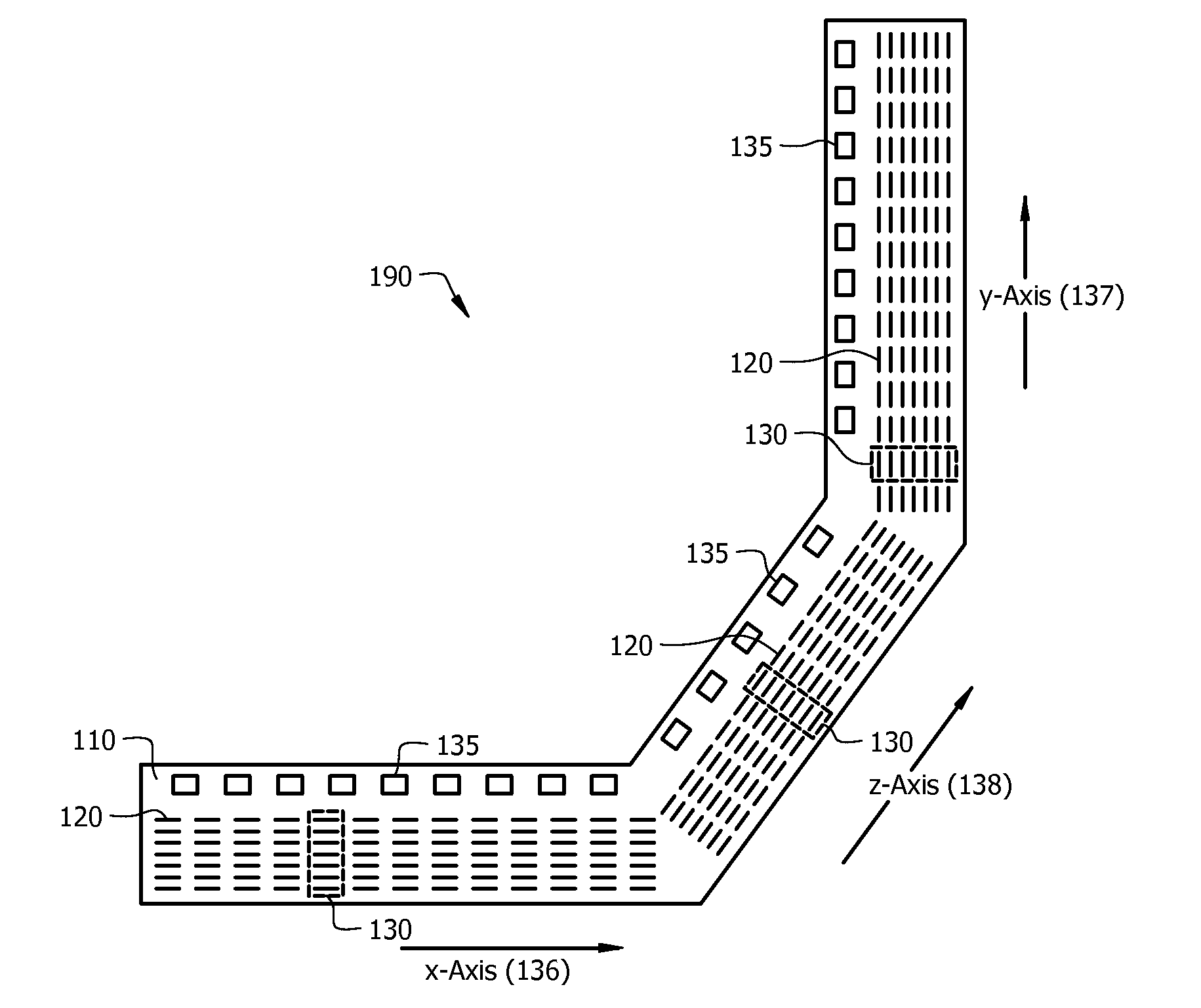
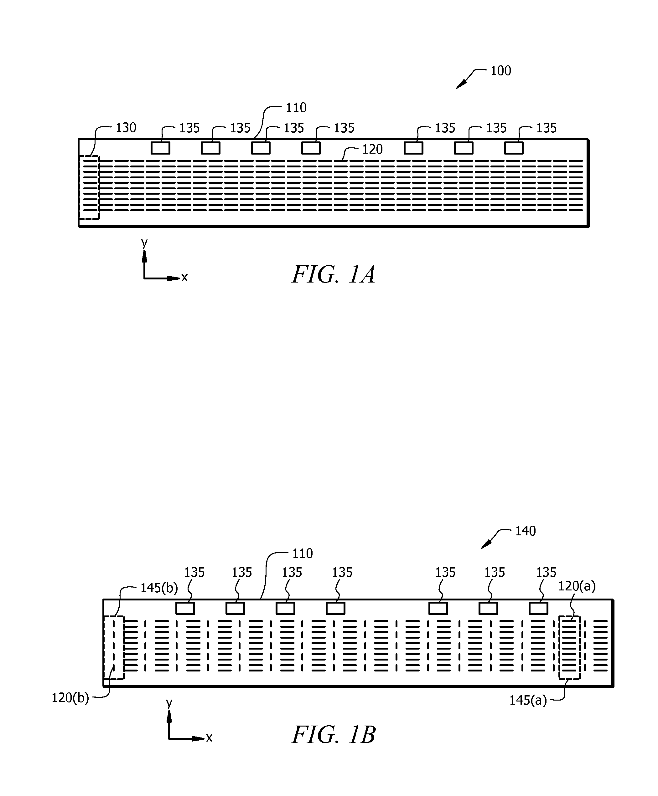
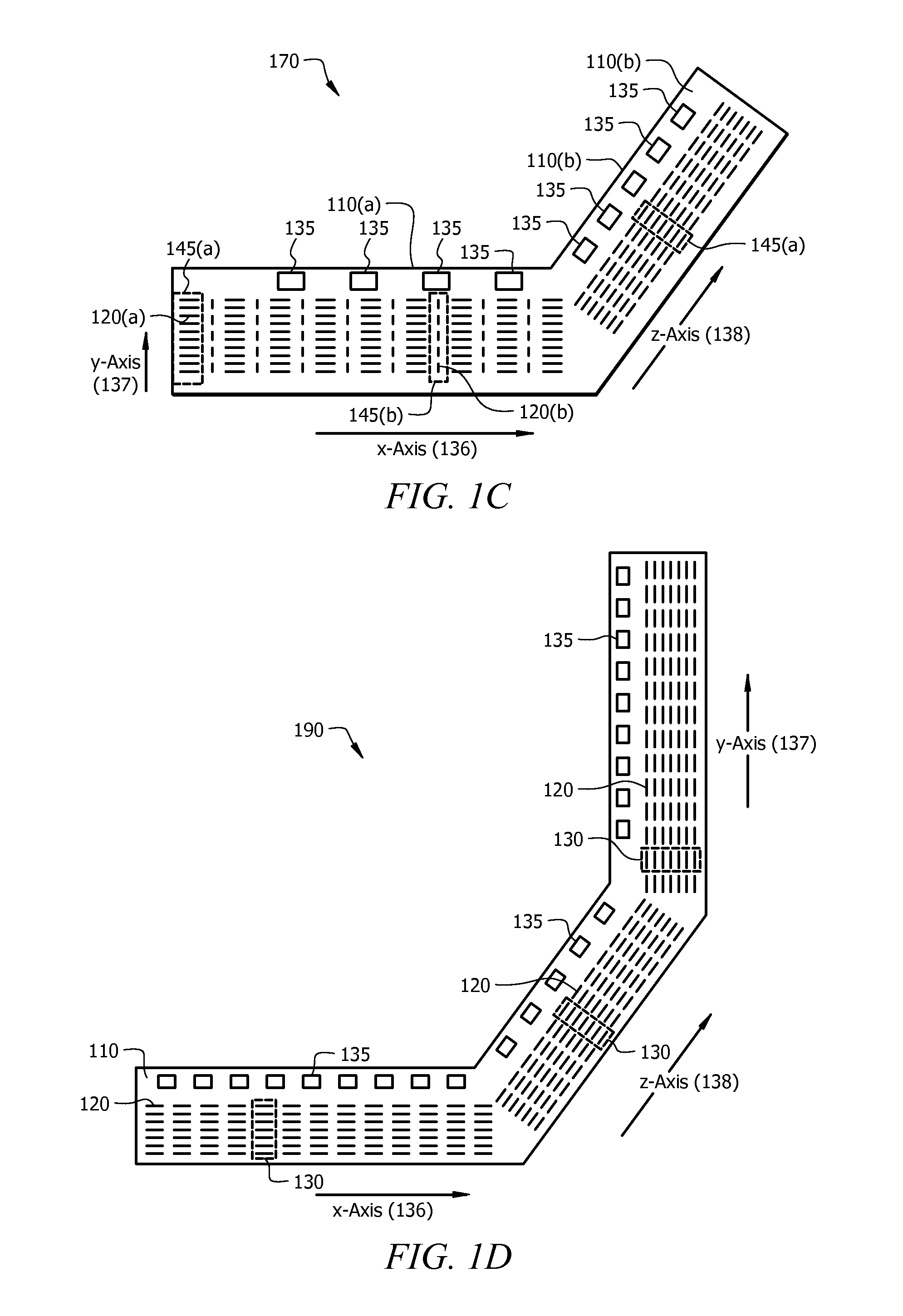
[0021]Disclosed embodiments are described with reference to the attached figures, wherein like reference numerals are used throughout the figures to designate similar or equivalent elements. The figures are not drawn to scale and they are provided merely to illustrate the disclosed embodiments. Several aspects are described below with reference to example applications for illustration. It should be understood that numerous specific details, relationships, and methods are set forth to provide a full understanding of the disclosed embodiments. One having ordinary skill in the relevant art, however, will readily recognize that the disclosed embodiments can be practiced without one or more of the specific details or with other methods. In other instances, well-known structures or operations are not shown in detail to avoid obscuring the disclosed embodiments. The disclosed embodiments are not limited by the illustrated ordering of acts or events, as some acts may occur in different orde...


PUM

PropertyMeasurementUnit
diameteraaaaaaaaaa
diameteraaaaaaaaaa
diameteraaaaaaaaaa

Abstract

A nanowire magnetic sensor includes an array of magneto-resistive (MR) nanosensors with each MR nanosensor including a set of MR nanowires that are all aligned in the same position for one direction. The substrate can be a flexible substrate bent into a circular configuration for compass applications. A plurality of individual nanosensors can be connected into resistive Wheatstone bridge configurations by metallization.

Description

CROSS REFERENCE TO RELATED APPLICATIONS[0001]This application is a continuation-in-part (CIP) of U.S. Non-provisional application Ser. No. 12 / 184,772 filed Aug. 1, 2008, which is herein incorporated by reference in its entirety.TECHNICAL FIELD[0002]Disclosed embodiments are generally related to magnetic sensors having a plurality of sensing elements.BACKGROUND[0003]Various types of equipment and systems for assisting in navigation and determining the location of a vehicle such as a boat, truck, automobile or airplane are known to the art. Such equipment and systems include various sensors for magnetic-effect sensing. Examples of common magnetic-effect sensors include Hall effect and magneto-resistive (MR) technologies. Such magnetic sensors can generally respond to a change in the magnetic field as influenced by the presence or absence of a ferromagnetic target object of a designed shape passing by the sensory field of the magnetic-effect sensor. The sensor can then provide an elect...

Claims


Application Information

Patent Timeline
Patent Type & Authority Applications(United States)
IPC IPC(8): G01R33/09G01C17/02G01R3/00
CPCG01B7/003G01B7/30G01C17/02Y10T29/49007G01R33/0023G01R33/09G01R33/0005
Inventor PECZALSKI, ANDRZEJ
Owner HONEYWELL INT INC
Why Eureka
Try Eureka