Apparatus for the coating of a substrate

a technology of apparatus and substrate, applied in the direction of coating, thermoplastic polymer dielectrics, printed circuit dielectrics, etc., can solve the problems of contact contamination, accurate application of protective lacquer, circuit boards with protective lacquer, etc., and achieve the effect of low viscosity

Active Publication Date: 2010-09-09
REHM THERMAL SYST
View PDF14 Cites 13 Cited by
  • Summary
  • Abstract
  • Description
  • Claims
  • Application Information

AI Technical Summary

Benefits of technology

[0014]The object of the present invention, then, is to specify an apparatus which does not have the disadvantages of the prior art. The apparatus is to allow a high-precision coating of, in particular, marginal contours and, moreover, to permit coating in which no splashes occur, the processing of high-viscosity and low-viscosity lacquers being possible without a change of nozzle. Moreover, a distribution of the coating material, for example, behind small legs of components on a circuit board is also to be possible.

Problems solved by technology

An appreciable problem in the coating of circuit boards with a protective lacquer is, in particular, that of applying the protective lacquer accurately.
Minor deviations or splashes of protective lacquer may lead very quickly to a contamination of contacts, this being reflected later in operating faults of the circuit.
However, the least impurities cause disruption in maintaining the lacquer film.
Substrates with higher obstacles, such as are presented, for example, by a printed circuit board module, cannot be coated satisfactorily, because spray shadows are formed behind each passed-over obstacle as a function of the speed and the component height.
The application width of the spray surface also changes with the unavoidably necessary change in the distance of the nozzle from the substrate.
This method is not suitable for applying low-viscosity substances and lacquers to printed circuit board modules, because excessive differences arise in the lacquer height.
The spray head cannot penetrate between high components because of its size.
Furthermore, during lacquering, filaments remain caught on components and interrupt the lacquering pattern, thereby generating splashes.
Moreover, marginal regions cannot be coated cleanly by means of this method.
The spray head cannot penetrate between high components because of its size.
In the case of higher-viscosity materials, the pulsation increases, with the result that splashes occur, because both air and accumulations of substance are formed in the spray nozzle and lead to an irregular discharge of material.

Method used


Image

  • Apparatus for the coating of a substrate
  • Apparatus for the coating of a substrate

Examples


Embodiment Construction

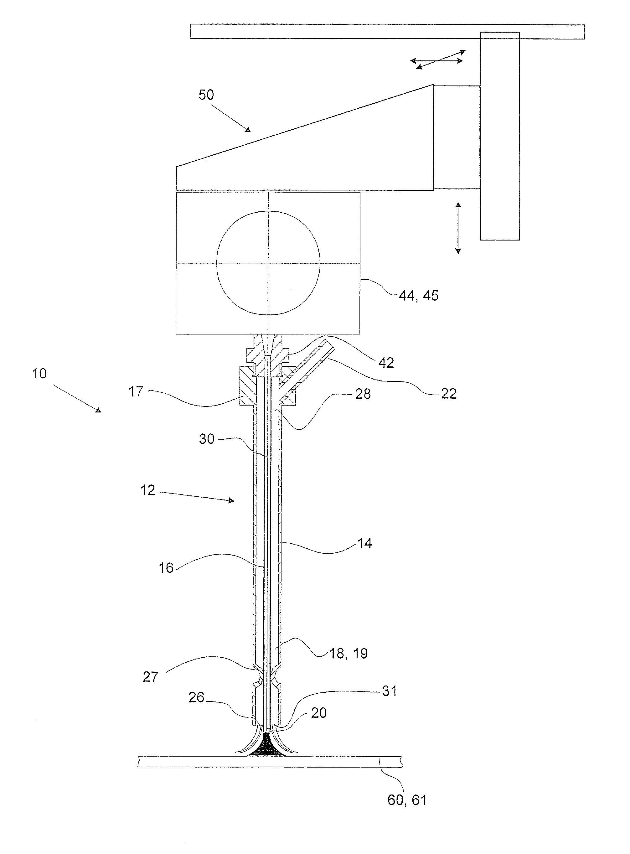
[0051]In FIG. 1, the nozzle region (coating head) of a coating plant is illustrated and is designated by reference symbol 10. A coating plant is used, for example, for applying a protective lacquer to a circuit board in order to protect the conductor tracks, for example, against moisture.

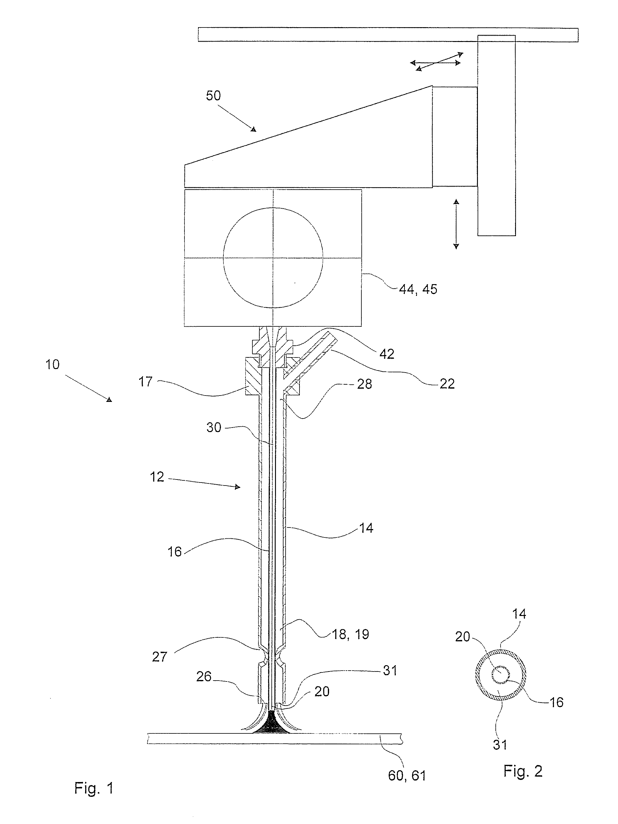
[0052]The coating plant comprises a nozzle device 12 which is constructed essentially from two tubes 14, 16 which terminate in each case at one end 28 in a head part 17, 42. The tube 14 lies on the outside (called the outer tube below) and surrounds the inner tube 16. The two tubes 14, 16 are arranged coaxially to one another, so that an annular region 18 is formed between the inner tube 16 and the outer tube 14. The mechanical connection of the two tubes 14, 16 may take place, for example, by the two head parts 17, 42 being screwed together.

[0053]As may be gathered from FIG. 1, the inner tube 16 terminates, offset with respect to the outer tube 14, so that a projecting end portion 20 is obtained.

[0...


PUM

PropertyMeasurementUnit
diameteraaaaaaaaaa
widthaaaaaaaaaa
distanceaaaaaaaaaa

Abstract

The invention relates to an apparatus for the coating of a substrate, in particular of a circuit board, with a material application device for applying a coating material and with a gas supplying device for the supply of a gaseous medium, the material application device having an inner tubular element, the gas supply device having an outer tubular element which is arranged coaxially to the inner tubular element and surrounds the latter, so as to form between the outer and the inner tubular element a gas supply duct which has an annular orifice at one end, the supply duct being configured so that the gaseous medium flows out, parallel to the coating material, through the annular orifice, in order, when it impinges on the substrate, to displace the applied coating material and thereby distribute it over the area. The apparatus is distinguished in that the material application device has a jet valve which, in a first operating mode, carries out a jetted supply of material into the inner tubular element.

Description

CROSS REFERENCES TO RELATED APPLICATIONS[0001]This application claims priority of German patent application DE 10 2009 013 379.8 filed on Mar. 9, 2009.BACKGROUND OF THE INVENTION[0002]The present invention relates to an apparatus for the coating of a substrate, in particular a circuit board with a device (material application device) for applying a coating material, in particular a protective lacquer, and with a device for supplying a gaseous medium (gas supply device), the material application device having an inner tubular element, the gas supply device having an outer tubular element which is arranged coaxially to the inner tubular element and surrounds the latter, so as to form, between the outer and the inner tubular element, a gas supply duct which has an annular orifice at one end, the supply duct being configured so that the gaseous medium flows out, parallel to the coating material, through the annular orifice, in order, when it impinges on the substrate, to displace the ap...

Claims


Application Information

Patent Timeline
Patent Type & Authority Applications(United States)
IPC IPC(8): H05K3/00B05C11/06
CPCB05B7/066B05C11/1034H05K3/0091H05K2203/081H05K2201/0129H05K2203/0126H05K3/28
Inventor KLINGEL, WOLFGANG
Owner REHM THERMAL SYST
Why Eureka
Try Eureka