Method for conveying a metered hydraulic volume in a vehicle braking system by means of an electrically driven motor pump assembly and vehicle braking system

a technology of electrical drive and metered hydraulic volume, which is applied in the direction of positive displacement liquid engine, pump control, vehicle components, etc., can solve the problems of complex design of other consumers and only short time period of pump motor control, and achieve the effect of small hydraulic volume, high clock frequency of control, and small volum

Active Publication Date: 2016-06-02
CONTINENTAL TEVES AG & CO OHG
View PDF8 Cites 0 Cited by
  • Summary
  • Abstract
  • Description
  • Claims
  • Application Information

AI Technical Summary

Benefits of technology

[0017]Preferably, it is provided that an electric control of the motor pump assembly is carried out in a pulse-width modulated manner, in particular with a clock frequency of at least 1 kHz. A pulse-width modulated control is an option for the variable control of an electric consumer which is relatively simple and, in particular, low-cost. The higher the clock frequency of the control, the greater the sensitivity with which it is carried out. Clock frequencies of 1 kHz and higher have proven sufficient for ensuring a quiet and even start of the delivery mode.
[0018]In addition, it is preferred that the time interval is infinitesimal. This results in the advantage that the delivery mode is aborted again immediately after it starts, whereby only a very small hydraulic volume is delivered. As a result, in turn, the delivered hydraulic volume can be highly precisely metered.
[0019]It is provided that the reduction is detected by observing a gradient of the motor current. This results in the advantage that the reduction can be reliably detected in a simple manner on the basis of the sign of the gradient, also in the case of relatively low motor currents. In this case, the occurrence of a negative gradient signals the reduction in the motor current. In this case, it is provided, in particular, that the negative gradient is formed and observed with an electronic circuit arrangement designed for this. This circuit arrangement can be designed, for example, as a relative current measuring circuit, which is also used, in principle, in a number of known braking control devices for detecting the motor current. In addition, it has proven advantageous, however, to provide this relative current measuring circuit with a low-resistance measuring resistor, which can also be designed as conductor path resistance in order to reduce costs. The gradient can also be formed in a hardware-based manner rather than by means of a software algorithm, wherein, in the former case, immediately after the gradient is formed, an interrupt is generated and the gradient is transmitted to a software algorithm designed for this.
[0020]In addition, it is provided that the method is carried out only in a single brake circuit of a multicircuit vehicle braking system. This results in the advantage that the occurring vehicle deceleration is reduced or, in the case of a double-circuit vehicle braking system, is substantially halved. The vehicle deceleration can therefore be set with greater sensitivity and can be controlled more exactly.
[0021]In particular, it is further provided that an isolating valve and a switchover valve of a brake circuit of the multicircuit vehicle braking system, whose electric motor of the motor pump assembly is not acted upon with the motor voltage ramp, are open. It is therefore ensured that braking pressure is not built up in this brake circuit and, therefore, a vehicle deceleration is not effected. This further improves the sensitive controllability of the vehicle deceleration. In particular in the case of a so-called diagonal division of the brake circuits of a double-circuit vehicle braking system, the further advantage results that the occurrence of alternating torques and, therefore, a transfer of vibrations to the steering can be avoided.
[0022]The method according to the invention is preferably distinguished by an angular position of the motor and / or the pump being determined by means of the motor voltage, the motor current, and a certain hydraulic pressure in the vehicle braking system. An energy input into the motor pump assembly can be easily determined via the motor current and the motor voltage when the delivery mode starts. With consideration for the hydraulic pressure prevailing in the vehicle braking system, a change in the angular position of the motor or the pump can therefore be determined, and so, in turn, the present angular position can be determined on the basis of the last known angular position. The advantage therefore results that an angular-position sensor is not required, which helps to reduce the production complexity and costs for the motor pump assembly.

Problems solved by technology

In the methods and devices known from the prior art, however, in order to set small and minimal braking pressures or to deliver relatively small hydraulic volumes of the pump motor, it is disadvantageous that the pump motor is controlled only for a short time period, although at full load.
The high inrush currents associated therewith induce current and voltage fluctuations in the entire vehicle electrical system, which can result in disturbances of the other consumers of the vehicle electrical system or requires a correspondingly reliable and, therefore, complex design of the other consumers.

Method used


Image

  • Method for conveying a metered hydraulic volume in a vehicle braking system by means of an electrically driven motor pump assembly and vehicle braking system
  • Method for conveying a metered hydraulic volume in a vehicle braking system by means of an electrically driven motor pump assembly and vehicle braking system

Examples


Embodiment Construction

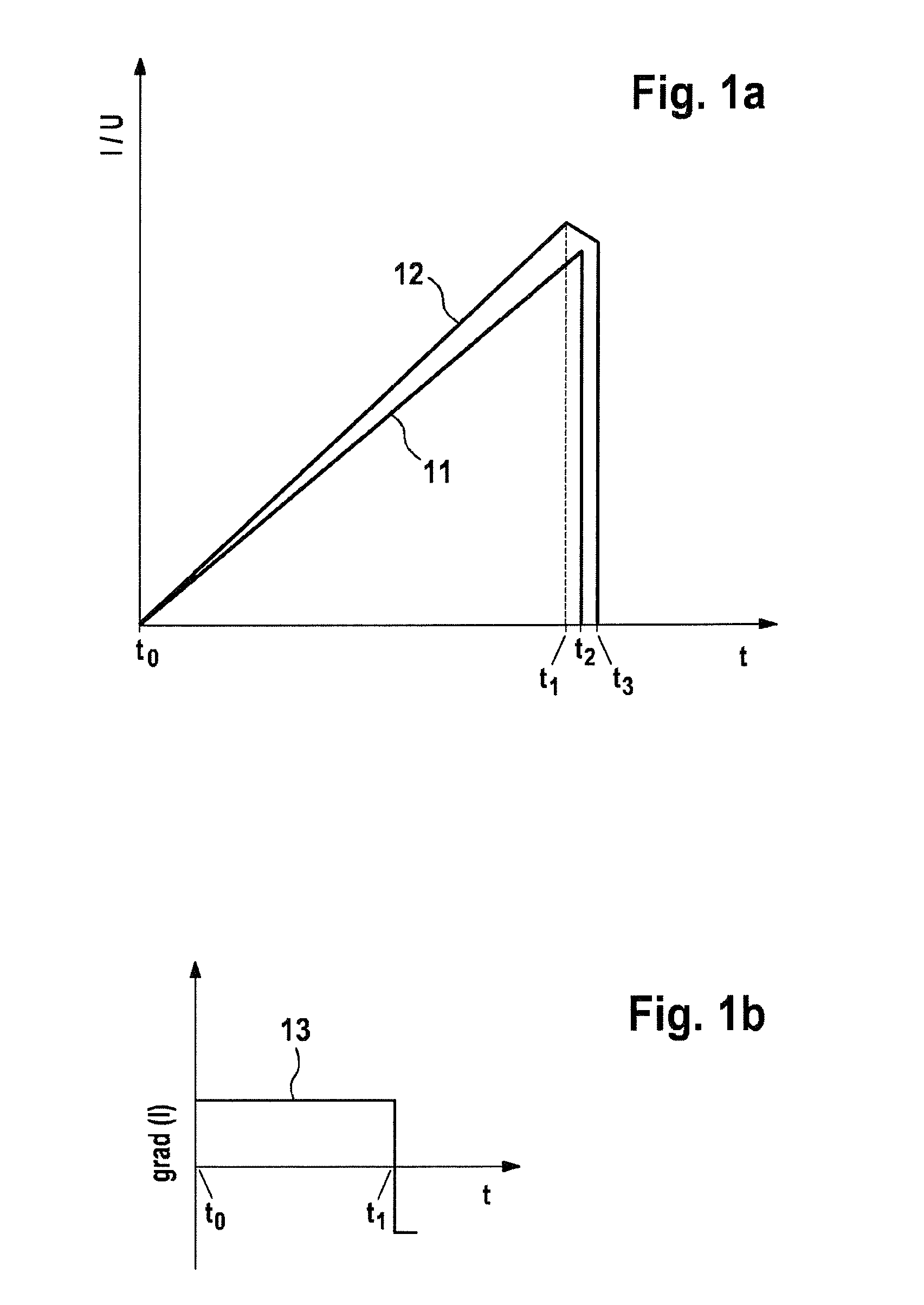
[0030]FIG. 1a shows current I and voltage U of the motor over time t, wherein curve 11 describes the motor voltage and curve 12 describes the motor current. In this case, the movement along the motor voltage ramp begins at the time to and is depicted by the rise of curve 11 in the interval from t0 to t2. The motor current also rises in curve 12, in proportion to the rise of curve 11, although only in the interval from t0 to t1. At the time t1, the generated motor torque exceeds the sum of drag torque, breakaway torque, and friction torque of the motor pump assembly, whereby the delivery mode of the motor pump assembly starts. This, in turn, results in a breakdown of the motor current at the time t1. Since a gradient of the motor current is formed and observed, the breakdown or the reduction in the motor current is detected on the basis of the change in the sign of the gradient, which is now negative. Immediately after the reduction in the motor current has been detected, i.e., after...


PUM


Abstract

A method for conveying a metered hydraulic volume in a vehicle braking system by an electrically driven motor pump assembly, wherein a mechanical pump of the motor pump assembly is driven by an electric motor of the motor pump assembly. A rising motor voltage ramp is applied to the electric motor, a motor current being detected, and a conveying mode of the motor pump assembly starting as soon as a motor torque generated by the motor current exceeds a total of drag torque, breakaway torque and friction torque of the motor pump assembly. The motor current reduces when the conveying mode starts. The method is characterized in that, when a reduction in the motor current is detected after a specified time interval has elapsed, a motor voltage is reduced to a value which ends the conveying mode. The invention further relates to a vehicle braking system.

Description

CROSS REFERENCE TO RELATED APPLICATIONS[0001]This application is the U.S. National Phase Application of PCT International Application No. PCT / EP2014 / 059956, filed May 15, 2014, which claims priority to German Patent Application No. 10 2013 209 890.1, filed May 28, 2013, the contents of such applications being incorporated by reference herein.FIELD OF THE INVENTION[0002]Method for delivering a metered hydraulic volume in a vehicle braking system by means of an electrically driven motor pump assembly and vehicle braking system[0003]The invention relates to a method for delivering a metered hydraulic volume in a vehicle braking system by means of an electrically driven motor pump assembly and to a vehicle braking system.BACKGROUND OF THE INVENTION[0004]The braking-related comfort and safety systems of motor vehicles, such as, for example, antilock braking systems, driving stability control systems, distance control systems, or rollover prevention systems, are controlled with increasing...

Claims


Application Information

Patent Timeline
Patent Type & Authority Applications(United States)
IPC IPC(8): B60T8/40
CPCB60T8/405B60T8/4059F04B49/06
Inventor KUTZNER, MICHAELTREIB, ALEXANDERSCHROTH, HANSHANDKE, PETERAKBARI-NAMWAR, ABOLFAZL
Owner CONTINENTAL TEVES AG & CO OHG
Why Eureka
Try Eureka