Method and device for tank ventilation of a fuel tank of a vehicle

a technology for fuel tanks and vehicles, applied in the direction of machines/engines, mechanical equipment, transportation and packaging, etc., can solve the problems of significant reduction of the purge air volume that can be achieved, limited capacity of activated carbon filters, and dependence on the purge air introduced into the intake manifold, so as to achieve reliable and even more optimal ventilation and simple and reliable combination

Inactive Publication Date: 2020-06-04
VOLKSWAGEN AG
View PDF8 Cites 0 Cited by
  • Summary
  • Abstract
  • Description
  • Claims
  • Application Information

AI Technical Summary

Benefits of technology

[0017]A provision is also made in another preferred embodiment of the invention that the purging device comprises at least one purge air pump. A pump can be controlled in a particularly targeted and hence need-based manner in combination with the control device, so that the aforementioned advantages can be implemented even better.
[0018]Moreover, a provision is made in another preferred embodiment of the invention that the at least one purge air pump can be driven electrically. Electrical operation not only makes possible the uniquely targeted control in terms of optimal achievement of the aforementioned advantages, but also allows for an especially simple and reliable combination with the proposed control device.
[0019]Furthermore, in another preferred embodiment of the invention, a provision is made that the control device comprises at least one pressure and temperature sensor that is arranged between purging device and air supply system or comprises at least two pressure and temperature sensors, with a pressure and temperature sensor being arranged in a connecting line between fuel tank and fuel vapor collecting device, and with a respective pressure and temperature sensor being arranged between purging device and air supply system. The information to be additionally obtained, which make corresponding inferences to be drawn about a respective operating state, thus serve the function of ensuring an even more reliable and even more optimal ventilation of the fuel tank and / or of the fuel vapor collecting device that is arranged downstream from the tank.

Problems solved by technology

Since the loading capacity of activated carbon filters is limited, they must be purged from time to time with a stream of air.
However, this combination significantly reduces the purge-air volume that can be achieved.
One disadvantage of the concept presented above is that the purge air that is introduced into the intake manifold is dependent on the prevailing level of negative pressure.
In addition, the purge gas that is introduced upstream from the exhaust gas turbocharger in combination with the Venturi nozzle only results from the pressure delta over precisely this Venturi nozzle that is used.
In this case, the working point of the passive-acting Venturi nozzle is optimal at only one operating point—that is, a maximum volume flow is established only at a specific pressure delta. Furthermore, the use of a Venturi nozzle causes an artificial “leak” in the charge air path, since the drive current is permanently unregulated.
However, the compromise calibration leads to losses in the maximum achievable purge-air volume, so that the system is not operated optimally in terms of the proper purge air.
Therefore, this publication does not disclose operation of a control device that is designed to at least partially regulate at least one first purge air stream and / or one second purge air stream, and that a fuel vapor collecting device is then ventilated via the at least one first purge air line and / or via the second purge air line, with a quantity distribution of an overall purge air stream that is composed of the at least one first and the at least second purge air stream to the first and second purge air line being controlled by means of the control device and an active control system of a purging device.

Method used


Image

  • Method and device for tank ventilation of a fuel tank of a vehicle
  • Method and device for tank ventilation of a fuel tank of a vehicle
  • Method and device for tank ventilation of a fuel tank of a vehicle

Examples


Embodiment Construction

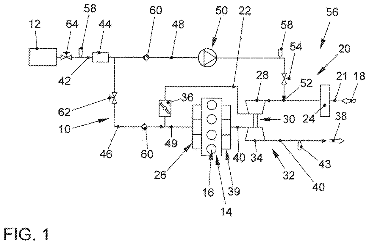
[0037]FIG. 1 shows a block diagram of a device 10 for tank ventilation of a fuel tank 12 of a vehicle that is not shown in an installed state. In other words, selected components of the vehicle are thus identifiable, so that the device 10 is illustrated schematically as being appropriately coupled with or connected to these components. As an additional component of the vehicle, an internal combustion engine 14 can also be seen which can be operated with fuel, for example gasoline, from the fuel tank 12. As stated, the fuel is stored in the fuel tank 12, it being possible for the fuel tank 12 to be refueled via a filler neck (not shown in further detail).

[0038]During operation, the fuel is then supplied from the fuel tank 12 via a fuel line (also not shown in further detail) by means of a fuel pump to the internal combustion engine 14, where it is distributed by means of an injection system (also not shown in further detail) to the cylinders 16 of the engine 14. Injection valves of t...


PUM


Abstract

The invention relates to a method and device for tank ventilation of a fuel tank of a vehicle. A first and a second purge air line are to be respectively connected to a fuel vapor collecting device that is arranged downstream from a fuel tank, the first line being connected to an intake manifold and the second line being connected to an air supply system of a supercharging unit. A purging device is additionally provided in the second purge air line. Operating a control device that is designed to at least partially regulate the at least one first purge air flow and/or the second purge air flow ultimately results in venting of the fuel vapor collecting device, with a quantity distribution of an overall purge air stream to the first and second purge air line being controlled by means of the control device and an active control system of a purging device.

Description

FIELD OF THE INVENTION[0001]The invention relates to a method for tank ventilation of a fuel tank of a vehicle and to a device for tank ventilation of a fuel tank of a vehicle.BACKGROUND OF THE INVENTION[0002]In order to operate internal combustion engines, a fuel is used which, before actual use, is stored in a fuel tank, for example. During storage in the fuel tank, evaporation of the fuel, in particular of low-molecular weight hydrocarbons, occurs to varying degrees as a function of an outside temperature and a free liquid surface of the fuel, for example. These evaporation products, commonly referred to as fuel vapors, are usually adsorbed in an activated carbon filter that is disposed in a vent line of the fuel tank. Since the loading capacity of activated carbon filters is limited, they must be purged from time to time with a stream of air. The streams of purge air loaded with fuel vapors and desorbed by the filter must not be discharged untreated into the environment due to l...

Claims


Application Information

Patent Timeline
Patent Type & Authority Applications(United States)
IPC IPC(8): F02M25/08B60K15/035
CPCF02M25/0836B60K15/03504B60K2015/03514B60K2015/0348B60K2015/03571
Inventor HACKMANN, PHILIPPWODAUSCH, JENSFRÖHLICH, BJÖRN
Owner VOLKSWAGEN AG
Why Eureka
Try Eureka