

Heat exchanger
a technology of heat exchanger and heat exchanger plate, which is applied in the direction of soldering apparatus, manufacturing tools, light and heating equipment, etc., can solve the problems of unavoidable defects, heavy weight, and aluminum brazing is apt to be more complicated
- Summary
- Abstract
- Description
- Claims
- Application Information
AI Technical Summary
Problems solved by technology
Method used
Image

Examples
first embodiment
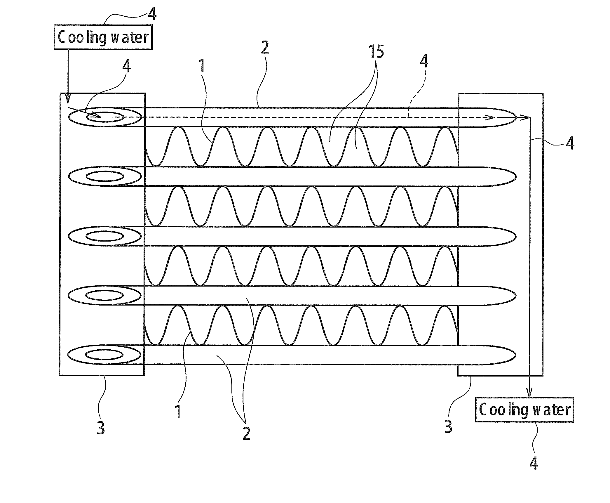
The Heat Exchanger
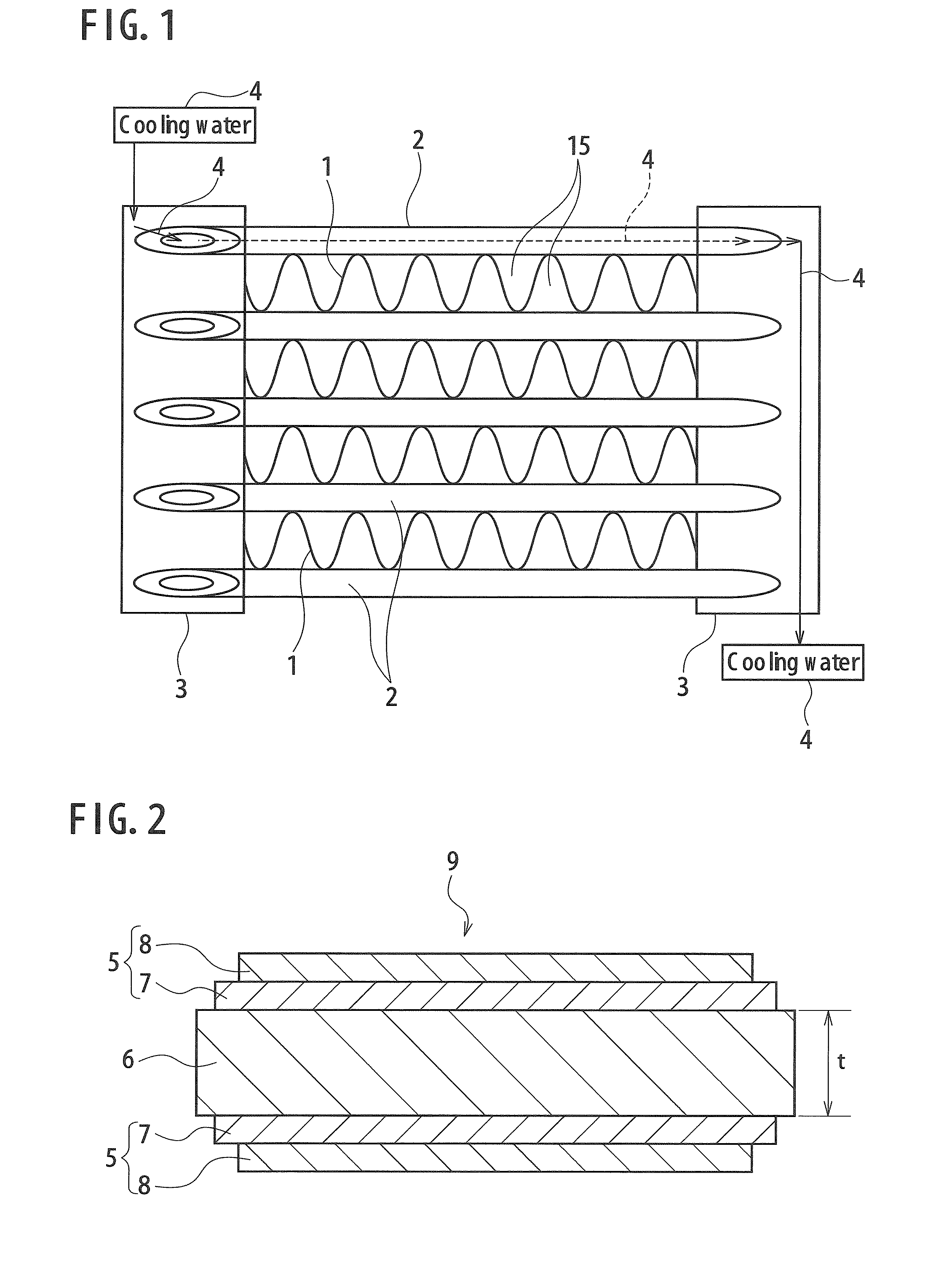
[0036]In the heat exchanger according to the first embodiment, the fin member 1 is formed by folding and bending a fin plate material 9, an example of which is shown in FIG. 2, into a wave shape, and is disposed in a state of being interposed between adjacent two tube members 2, 2, and each part of the fin member 1 brought into contact with the tube member 2 is surely joined to the tube member 2. Further, the fin member 1 is disposed in a state of being interposed between right and left tank members 3. The fin member 1 and the tank member 3 may be joined each other or may be simply set in contact with each other mechanically.
[0037]The fin plate material 9 has a solder wetting film layer 5 containing copper (Cu), on approximately the whole surface or at least in a part of the fin substrate 6 made of aluminum (Al) or an alloy mainly composed of aluminum (Al) where the fin member 1 and the tube member 2 are joined each other.
[0038]According to a preferable numerical a...
second embodiment
The Heat Exchanger
[0060]In the heat exchanger according to the second embodiment, the fin member 1 as shown in FIG. 7 is used. Namely, the fin member 1 is formed by further adding the solder film layer 12 to the outermost surface of the fin plate material 9 of the first embodiment, and folding and bending this fin plate material 9 into a prescribed wave shape. The fin member 1 is disposed in such a manner as being sandwiched between the adjacent two tube members 2 and 2, so that each part where the tube member 2 and the fin member 1 are brought into contact with each other, is surely joined each other. Moreover, the fin member 1 is disposed in such a manner as being sandwiched between right and left tank members 3. The fin member 1 and the tank member 3 may be joined each other or may be set in a state of simply being brought into contact with each other mechanically.
[0061]Further specifically, the fin member 1 has the solder wetting film layer 5 containing copper, on approximately ...
example 1
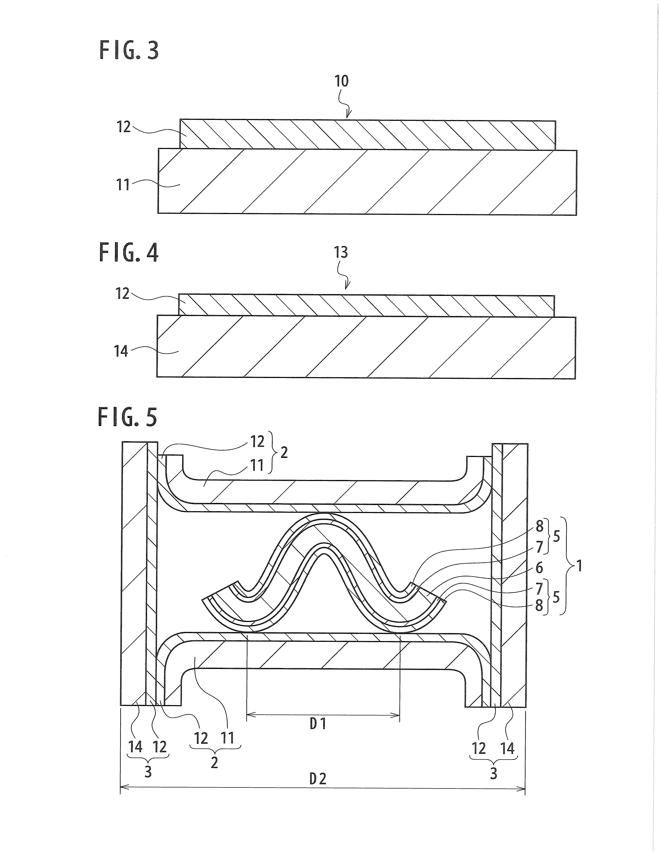
[0079]According to the first embodiment, as example 1, the trial model of the heat exchanger having the structure as shown in FIG. 5 and FIG. 6 was manufactured and its joint state was evaluated.
[0080]First, the fin member 9 having the structure as shown in FIG. 2, the tube plate material 10 having the structure as shown in FIG. 3, and the tank member 13 having the structure as shown in FIG. 4 were manufactured.
[0081]As the fin substrate 6, being the substrate of the fin plate material 9, a hard material of A5052, being an Al—Mg alloy (Al—Mg based alloy defined in JIS, containing 2.2 to 2.8 wt % of Mg) having thickness of t=50 μm, width of W1=16 mm, and length of 40 mm, was used.
[0082]As the tube substrate 11, being the substrate of the tube plate material 10, a brass material having a composition of Cu—35 wt % Zn, and having thickness of 230 μm, width W2=20 mm, and length of 80 mm, was used.
[0083]Also, as the tank substrate 14, being the substrate of the tank plate material 13, the...
PUM
| Property | Measurement | Unit |
|---|---|---|
| thickness | aaaaa | aaaaa |
| thickness | aaaaa | aaaaa |
| thickness | aaaaa | aaaaa |
Abstract
Description
Claims
Application Information