Knockdown container
a container and knocking technology, applied in the field of knocking containers, can solve the problems of imposing a large burden on production costs, needing to replace pallets with new ones, and increasing the width of the constricted part of the transfer passage, etc., and achieve the effect of convenient replacement and more reliable holding together
- Summary
- Abstract
- Description
- Claims
- Application Information
AI Technical Summary
Benefits of technology
Problems solved by technology
Method used
Image

Examples
first embodiment
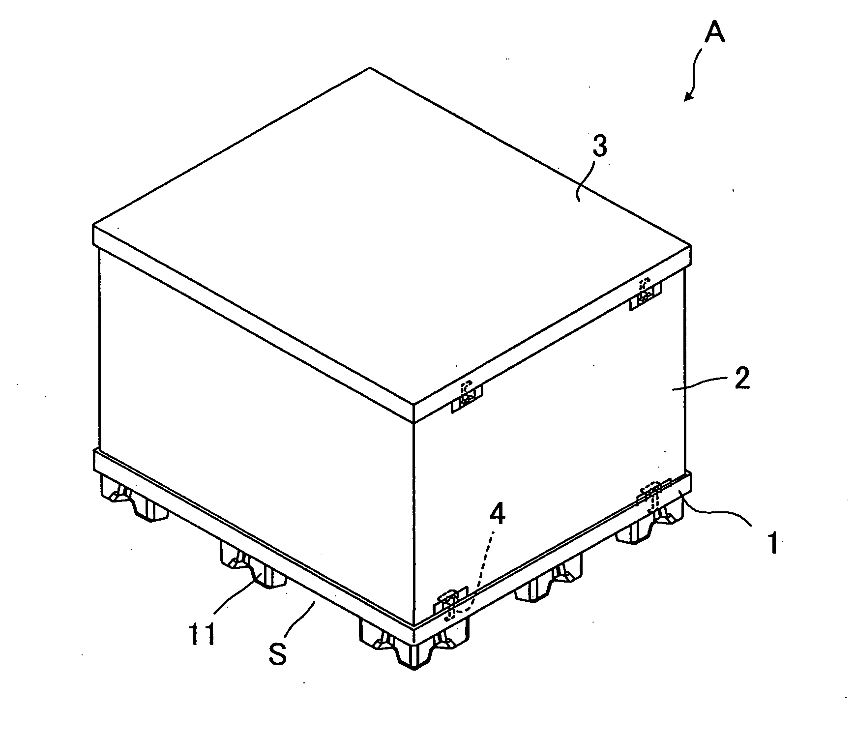
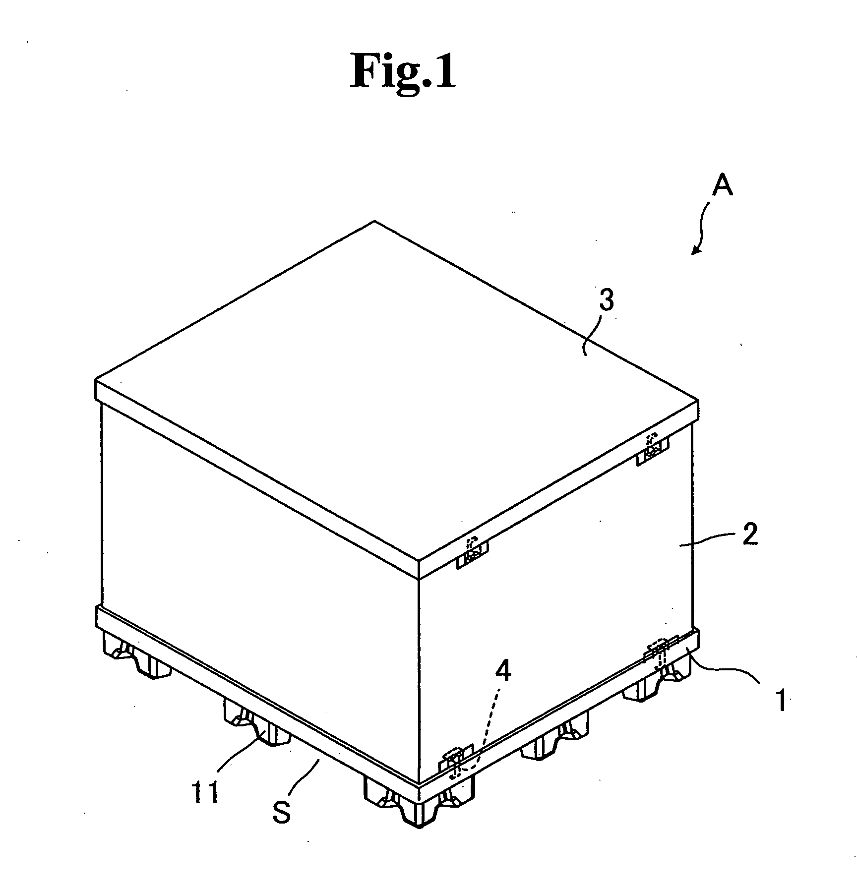
[0065]One embodiment of the present invention will be descried with reference to the drawings. FIG. 1 is a schematic perspective view showing a knockdown container according to this embodiment. As shown in FIG. 1, the knockdown container A according to this embodiment is made up of a pallet 1 forming a bottom, sleeves 2 fitted in grooves provided at the peripheral portions of the pallet to form side walls, and a lid part 3 placed on top of the sleeves. Hook members 4 are attached to each sleeve, while receptacle portions (not shown) are formed in the pallet 1 to retain the hook members 4.
[0066]The pallet 1 includes leg portions 11 to form a space S for allowing a forklift fork to enter therebelow. These leg portions 11 form a space S between the ground and the pallet 1, so that the fork can easily enter into the space S. To move the knockdown container A according to this embodiment, the fork is inserted into the above-noted space S, and the above-noted knockdown container including...
second embodiment
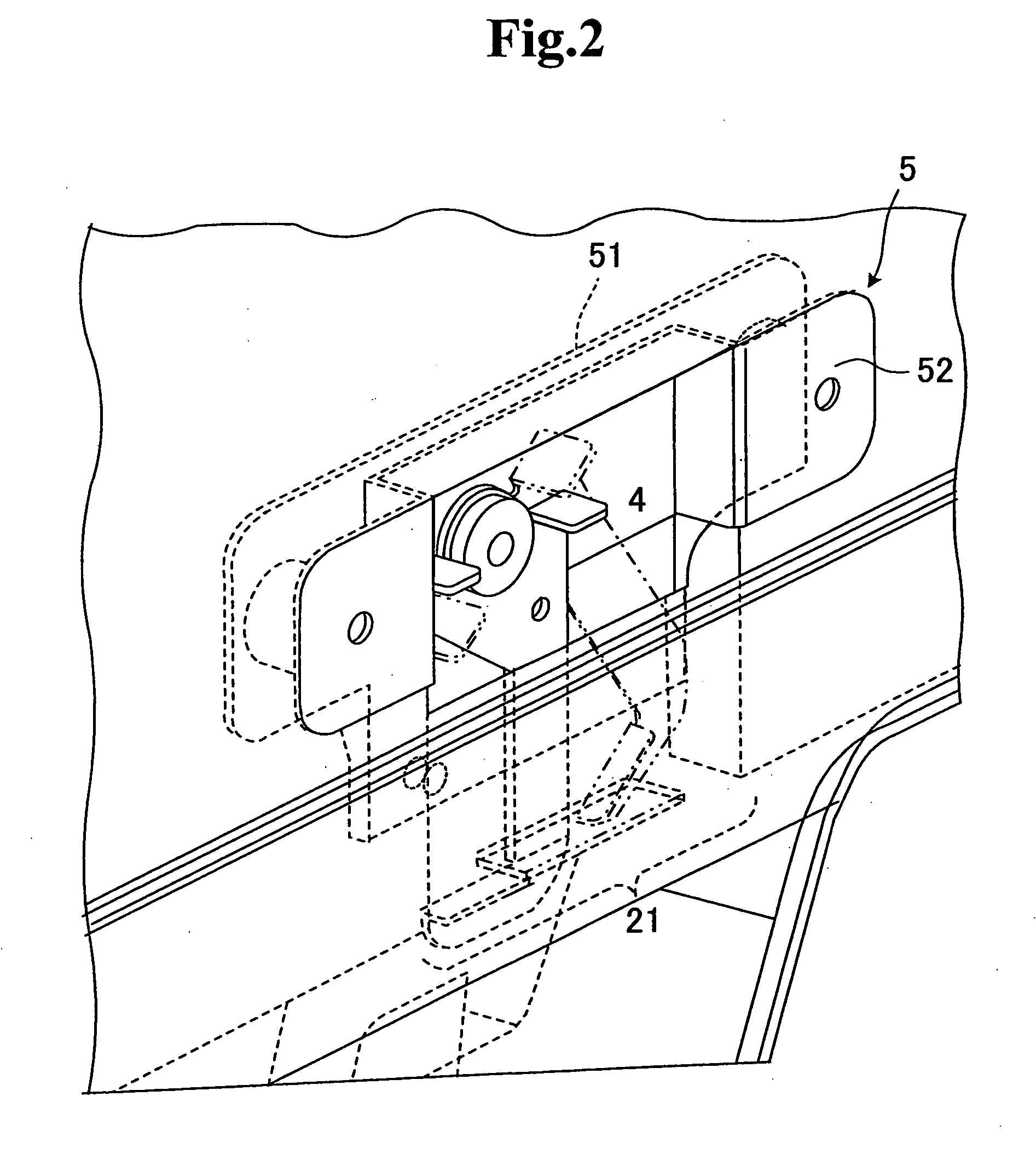
[0080]FIG. 6 is a schematic diagram showing, in enlargement, a state in the vicinity of the hook member in the knockdown container having hook members according to the embodiment of the invention. FIG. 7 is a schematic diagram of the state of FIG. 6 viewed from the opposite side of the sleeve. As shown in FIG. 6, the hook member 4 of the knockdown container with hook members according to this embodiment is in a rectangular plate shape, and the claw portion 42 is formed at the lower end of the hook member 4 by cutting away part thereof at a position a predetermined distance away from the bottom side of the hook member 4. Meanwhile, the receptacle portion 12 that engages with the claw portion 42 is formed in the pallet 1 as a tunnel-like opening in part of a bulged portion 14 protruded inside the groove, in which the sleeve 2 is fitted. The claw portion 42 engages with the receptacle portion 12 in the pallet 1 to fasten the pallet 1 and the sleeve 2 together. The hook member 4 is capa...
PUM
 Abstract
Description
Claims
Application Information
PatSnap Eureka turns technology decisions into work you can execute. Powered by our Innovation Knowledge Graph, it runs expert workflows across engineering, life sciences, materials and intellectual property. Get your review-ready output in minutes.


