Armature Core, Motor Using It, and Its Manufacturing Method

a manufacturing method and technology of a magnet core, applied in the field of motors, can solve the problems of limiting the shape of teeth, difficult to design such a high-density location, and complicated manufacturing process, and achieves high harmonic content of magnetic flux, high permeability, and large variations in magnetic flux density

Inactive Publication Date: 2010-09-09
DAIKIN IND LTD
View PDF10 Cites 61 Cited by
  • Summary
  • Abstract
  • Description
  • Claims
  • Application Information

AI Technical Summary

Benefits of technology

[0046]Thus, a dust core made of pressed magnetic powder having a small eddy-current loss is used for the teeth that have large variations in magnetic flux density, i.e., contains a high harmonic content of magnetic flux, especially in the proximity of an air gap. Further, a laminated steel sheet with high permeability and a high saturation magnetic flux density is used for the back yoke that maintains a relatively high magnetic flux density for a long period of time. Then, by burying the above-mentioned teeth axially to a certain depth in the back yoke or by burying the above-mentioned teeth in the back yoke to penetrate axially, the back yoke passes a large amount of magnetic flux almost in a plane that is orthogonal to the rotation axis. This prevents impairment of motor characteristics. Further, the presence of the first insulating material sandwiched between the back yoke and the coils to provide insulation between the back yoke and the coils prevents, at the joints between the teeth and the back yoke, the radii of the teeth made by machining from interfering with angular portions of holes formed in the back yoke.
[0047]Since the above-mentioned plurality of teeth are formed separately of a dust core, only small molding pressure is required, which prevents upsizing of equipment. Further, the positioning of the teeth by the back yoke results in good air-gap accuracy. Still further, although it has conventionally been difficult to install axial gap type motors for relatively high power applications such as compressors, the application of the motor according to the invention allows the adoption of axial gap type motors for such applications.

Problems solved by technology

However, patent document 1 has a problem that it limits the teeth shape because magnetic steel sheets stamped into the same shape are laminated.
However, if constraints are added to the flexibility of the teeth shape as described above, it becomes difficult to design such a high-density location.
However, for achieving complicated shape, more than one kind of stamping dies are necessary, which has a problem that the manufacturing process is complicated.
While patent document 3 has disclosed a technique for combining a dust core and a laminated steel sheet in radial gap type motors, this technique is not applicable to axial gap type motors because the axial gap type motors basically differ in the flow of magnetic flux from two-dimensional motors.

Method used


Image

  • Armature Core, Motor Using It, and Its Manufacturing Method
  • Armature Core, Motor Using It, and Its Manufacturing Method
  • Armature Core, Motor Using It, and Its Manufacturing Method

Examples


embodiment a1

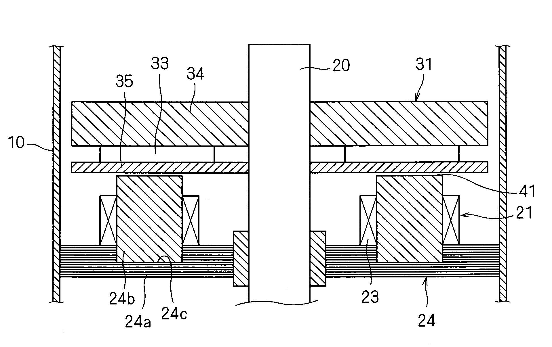
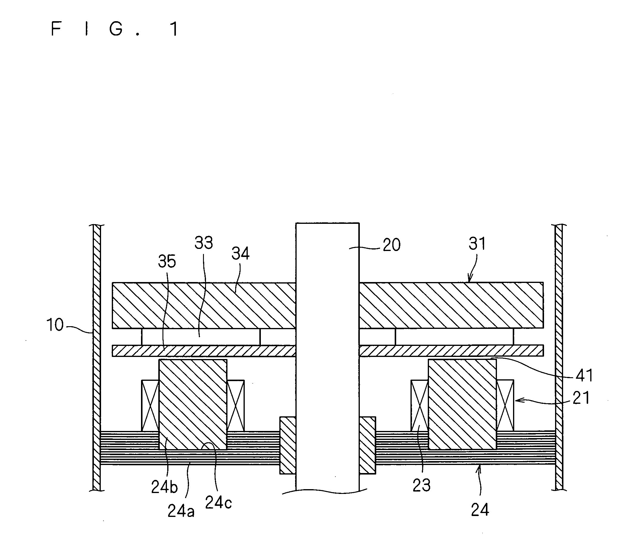
[0143]FIG. 1 is a cross-sectional view of the outlines of a motor according to embodiment A1, and FIG. 2 is an exploded perspective view of a stator of the motor shown in FIG. 1.

[0144]The motor according to this embodiment A1, as shown in FIG. 1, includes a stator 21, a rotor 31 located above this stator 21 with an air gap 41 therebetween, and a shaft 20 that is fixed to this rotor 31 and transmits a torque of this rotor 31 to a load and that extends out of this rotor 31 to be rotatably supported by a bearing (not shown). The above-mentioned rotor 31 rotates on the axis of the shaft 20, or a certain rotation axis.

[0145]The above-mentioned stator 21 includes a stator core 24 attached to the inside of a casing 10 by, for example, press fitting or shrink fitting, and coils 23 attached to this stator core 24.

[0146]The above-mentioned stator core 24 includes an annular ring-shaped back yoke 24a located so as to be generally orthogonal to the shaft 20, and teeth 24b located upright on the...

embodiment a2

[0186]FIG. 13 is a cross-sectional view of the outlines of a motor according to embodiment A2.

[0187]The motor according to this embodiment A2, as shown in FIG. 13, includes a rotor 431 attached to a shaft 420, and two stators 421 located on both axial sides of the rotor 431. The above-mentioned rotor 431 rotates on the axis of the shaft 420, or a certain rotation axis. These stators 421 each are the stator 421 shown in FIG. 9 according to embodiment A1. The above-mentioned rotor 431 includes two rotor plates 435 and a permanent magnet 433 located between those two rotor plates 435. Locating the stator 421 to sandwich the above-mentioned rotor 431 from both axial sides enhances flux linkage and improves output.

[0188]While the stators 421 of the motor according to the above-mentioned embodiment A2 are identical in configuration to the fourth alternative example shown in FIG. 9, the presence of the two back yokes 424 located at a certain distance inside the casing 10 have the effect of...

embodiment a3

[0199]FIG. 15 is a cross-sectional view of the outlines of a motor according to embodiment A3. The motor according to this embodiment A3, as shown in FIG. 15, includes the rotors 31 on both sides of a stator 621. In FIG. 15, wide end portions of the teeth 624b improve air-gap permeance.

[0200]As shown in FIG. 15, the plurality of teeth 624b of a stator core 624 have wide portions 624c provided on the sides facing the rotors 31, which increases the area that faces the rotors 31 and thereby enhances flux linkage. Further, attractive forces acting from the above-mentioned stator 621 on the rotors 31 on both axial sides can cancel thrust force acting on the rotors 31 and the shaft 20 and can also reduce force acting in the thrust direction on a bearing that supports the shaft 20.

[0201]At this time, the presence of the wide portions 624c at both the ends of the teeth 624b hinders the teeth 624b from being axially inserted into a back yoke 624a.

[0202]Thus, as shown in FIG. 16, the back yo...


PUM

PropertyMeasurementUnit
depthaaaaaaaaaa
stress relaxationaaaaaaaaaa
shapeaaaaaaaaaa

Abstract

An object is to enable simple manufacture of a motor, especially, a stator core or a field without impairment of motor characteristics. The motor includes a shaft, a rotor fixed to the shaft, and a stator including a stator core that faces the rotor with a certain space therebetween and coils that are attached to the stator core. The stator includes a back yoke, and the stator core having a plurality of teeth that are circumferentially placed in an axial end face of the back yoke so as to stand upright axially of the back yoke, and that are formed of a dust core made of pressed magnetic powder. The above-mentioned teeth are buried axially to a certain depth in the back yoke.

Description

TECHNICAL FIELD[0001]The present invention relates to a motor and a method of manufacturing a motor; a compressor; and an armature core and a technique for manufacturing an armature core.BACKGROUND ART[0002]Conventional motors include axial gap type motors in which a rotor and a stator face each other in a plane that is generally orthogonal to a rotation axis. In such axial gap type motors, the use of a core formed by laminating, in a direction of the rotation axis, thin plates (such as magnetic steel sheets) that are generally orthogonal to the rotation axis raises a problem that more eddy current is generated especially in teeth and in the vicinity thereof, because the direction of the lamination and a flow of magnetic flux become parallel.[0003]Japanese Patent Application Laid-open No. 2000-253635 (patent document 1) has employed a stator core formed by laminating H-shaped magnetic steel sheets in a circumferential direction.[0004]Japanese Patent Application Laid-open No. 2004-56...

Claims


Application Information

Patent Timeline
Patent Type & Authority Applications(United States)
IPC IPC(8): H02K1/18H02K1/02H02K15/02
CPCF04B39/00H02K1/02Y10T29/49009H02K21/24H02K1/148
Inventor ASANO, YOSHINARINAKAMASU, SHINKONDOU, TOSHINARI
Owner DAIKIN IND LTD
Why Eureka
Try Eureka