
Phase change device

a phase change and phase change technology, applied in non-linear optics, instruments, optics, etc., can solve the problems of relatively slow process of switching, large use or preference of buildings, and materials that cannot be controlled by the occupant of a room, so as to achieve rapid change of reflectivity and the effect of reducing the number of times

Inactive Publication Date: 2010-09-09
RGT UNIV OF CALIFORNIA
View PDF7 Cites 28 Cited by
  • Summary
  • Abstract
  • Description
  • Claims
  • Application Information

AI Technical Summary

Benefits of technology

[0011]By way of this invention, an improved switchable window is provided whereby its transmissivity/reflectivity may be rapidly changed using materials that rapidly undergo phase change under the influence of pulsed, transient heatin

Problems solved by technology

There are other classes of dynamic materials such as photochromic (darken with increasing incident UV light) or thermochromic (darken when the temperature increases above a certain threshold, e.g. about 65° C. for VO2), but these types of materials cannot be controlled by the occupant of a room and are therefore not widely used or preferred for buildings applications.
Since ion motion is involved, however, the process of switching is relatively slow, usually of the order of many seconds or minutes, before the desired change in the transmittance and / or reflectance of the material is observed.
However, besides slow switching speed, such systems based on ion intercalation have been shown to have a generally limited lifetime, which is especially true for the less mature material systems (i.e. those other than the tungsten oxide system).
Limited lifetime, slow switching speed, limited contrast, and relatively high cost have prevented broad market penetration of such energy efficient windows.

Method used


Image

  • Phase change device
  • Phase change device
  • Phase change device

Examples


Embodiment Construction

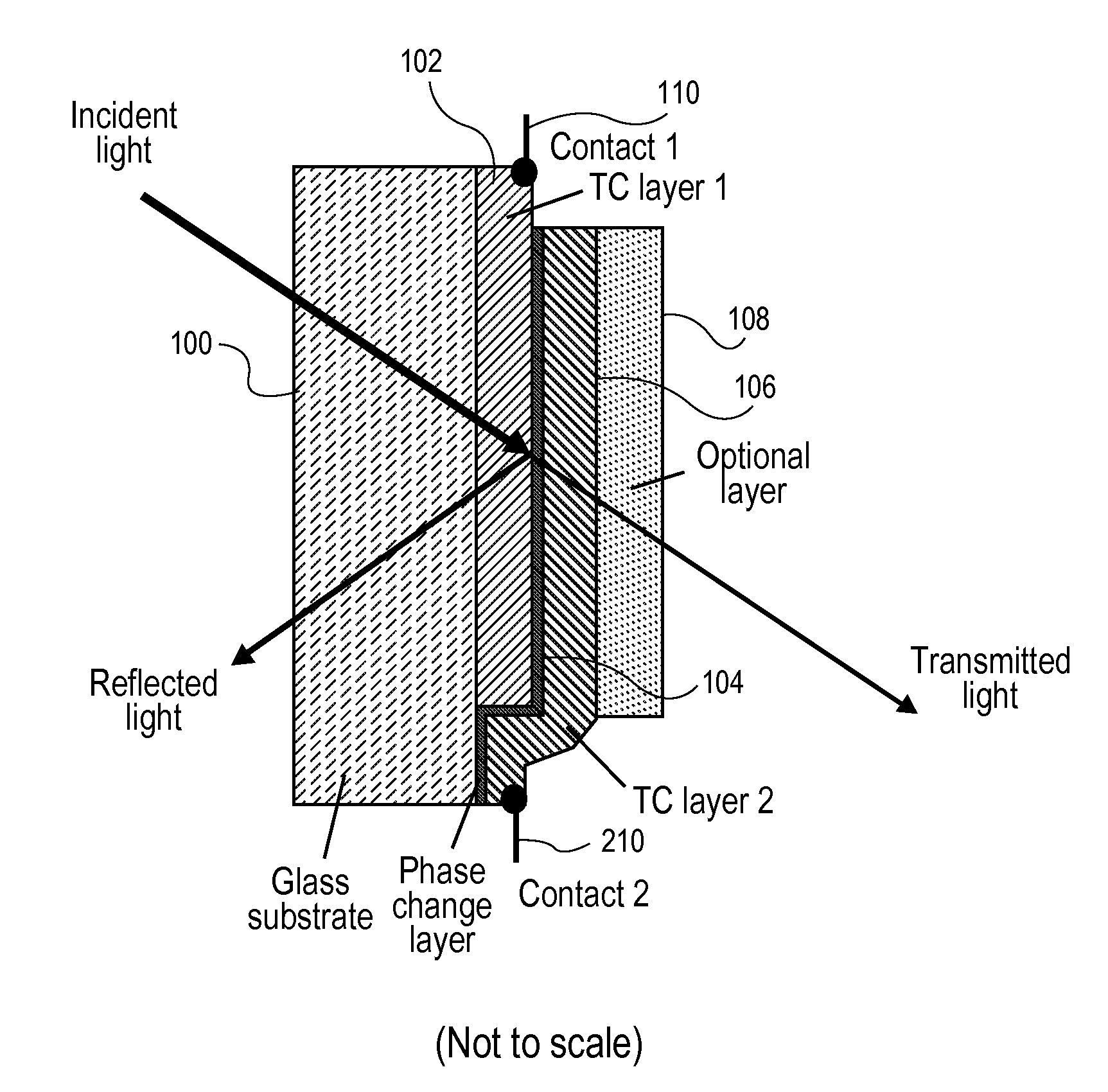
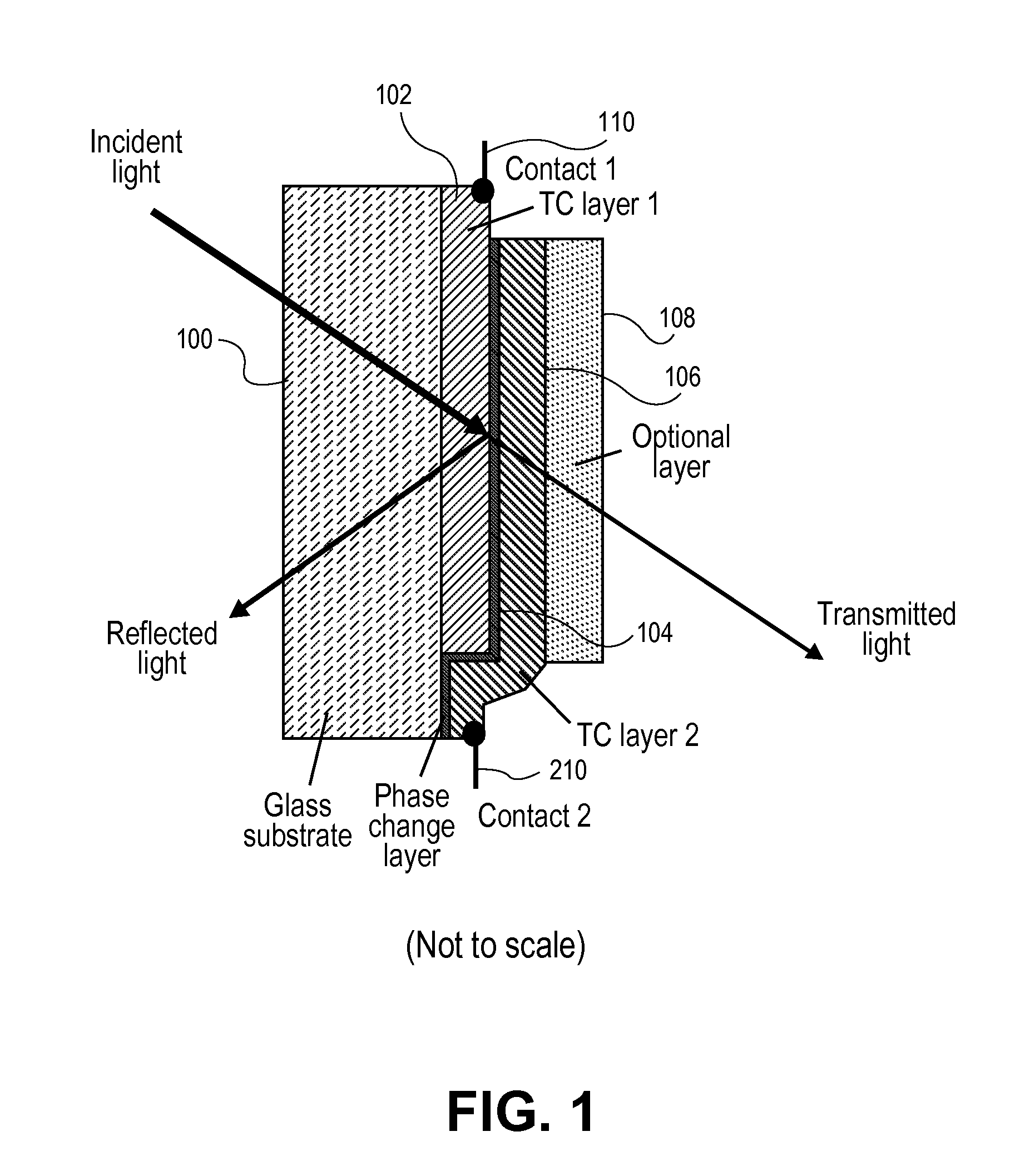
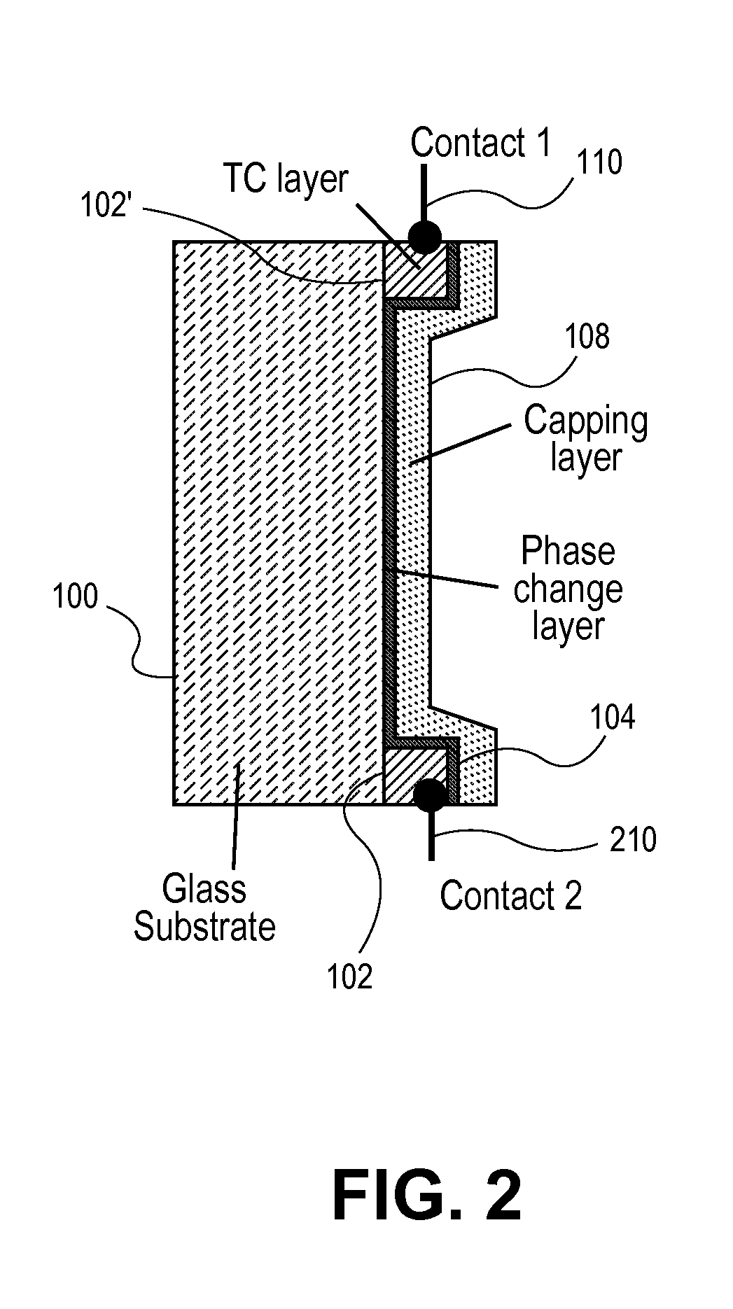
[0022]These and other objects and advantages of the present invention will become more fully apparent from the following description taken in conjunction with the accompanying drawings.

[0023]Described herein below is the use of a cost-effective, robust, layer system to be deposited on a transparent medium like glass where, for example, it can be incorporated into an affordable, energy-efficient insulated glass unit (IGU), the core of a modern window for residential and commercial buildings. Other potential applications include windows in vehicles, large area displays, roof panels, etc.

[0024]In the current invention, very thin films in the order of 10 nm of phase change materials of the type used in optical storage discs like DVD and Blu Ray are used for large areas where switching of the optical properties may be used to change the reflectivity of windows, such as used in residential and commercial buildings. The different optical properties of the phases are related to very differe...


PUM


Abstract

A phase change material is applied as a very thin film to a transparent substrate such as glass, which material when switched from the amorphous to the crystalline state and back again can affect the reflectivity / transmittance of the combined substrate-coating system. When used with glass panels in the fabrication of relatively large area window glass, the change in spectrally selective transmittance can be used to modulate the amount of sunlight passing through the glass, and thus reduce the amount of cooling required for an interior space in the summertime, and the amount of heating required of that same interior space in the wintertime, while also optimizing the use of visible daylight. Exemplary of a suitable phase change material for glass coating is GeSb or BiSn. Heating of the phase change material to initiate a change in phase can be provided by the application of electric energy, such as supplied from a pulsed power supply, or radiant energy, such as from a laser.

Description

CROSS REFERENCE TO RELATED APPLICATIONS[0001]This application claims priority to U.S. Provisional Patent Application Ser. No. 61 / 157,825, filed Mar. 5, 2009, and entitled Phase Change Device, Andre Anders inventor, the contents of said application incorporated herein by reference in its entirety and for all purposes.STATEMENT OF GOVERNMENTAL SUPPORT[0002]The invention described and claimed herein was made in part utilizing funds supplied by the U.S. Department of Energy under Contract No. DE-AC02-05CH11231. The government has certain rights in this invention.BACKGROUND OF THE INVENTION[0003]1. Field of the Invention[0004]This invention relates generally to phase change materials, and, more specifically, to dynamic windows incorporating phase change materials for regulation of their spectrally selective transmittance, and thus their energy efficiency.[0005]2. Description of the Related Art[0006]As part of an attempt to create more energy efficient buildings, there is a lot of interes...

Claims


Application Information

Patent Timeline
IPC IPC(8): G02F1/19
CPCG02F1/19G02F1/0147
Inventor ANDERS, ANDRE
Owner RGT UNIV OF CALIFORNIA
Learn More