Aircraft joint and bonding lead

a technology of aircraft and lead, applied in the direction of electrostatic charge, electrically conductive connections, emergency protective arrangements for automatic disconnection, etc., can solve the problem of static electricity build-up in aircraft fuel systems of one component, and achieve the effect of reducing the risk of sparking, preventing sparking, and high resistan

Active Publication Date: 2010-09-09
AIRBUS OPERATIONS LTD
View PDF9 Cites 21 Cited by
  • Summary
  • Abstract
  • Description
  • Claims
  • Application Information

AI Technical Summary

Benefits of technology

[0007]A further aspect of the invention provides a method of preventing sparking across a joint on an aircraft, the method comprising: electrically connecting components of the joint with each other with a bonding lead, the bonding lead having an electrical resistance between 100 kΩ and 10 MΩ; dissipating static charge between the components by means of the bonding lead; and pa...

Problems solved by technology

There is a risk in aircraft fuel systems of a build up of static electricity on one component in comparison to another component to which it is connected.
There is a risk that ...

Method used


Image

  • Aircraft joint and bonding lead
  • Aircraft joint and bonding lead
  • Aircraft joint and bonding lead

Examples


Embodiment Construction

)

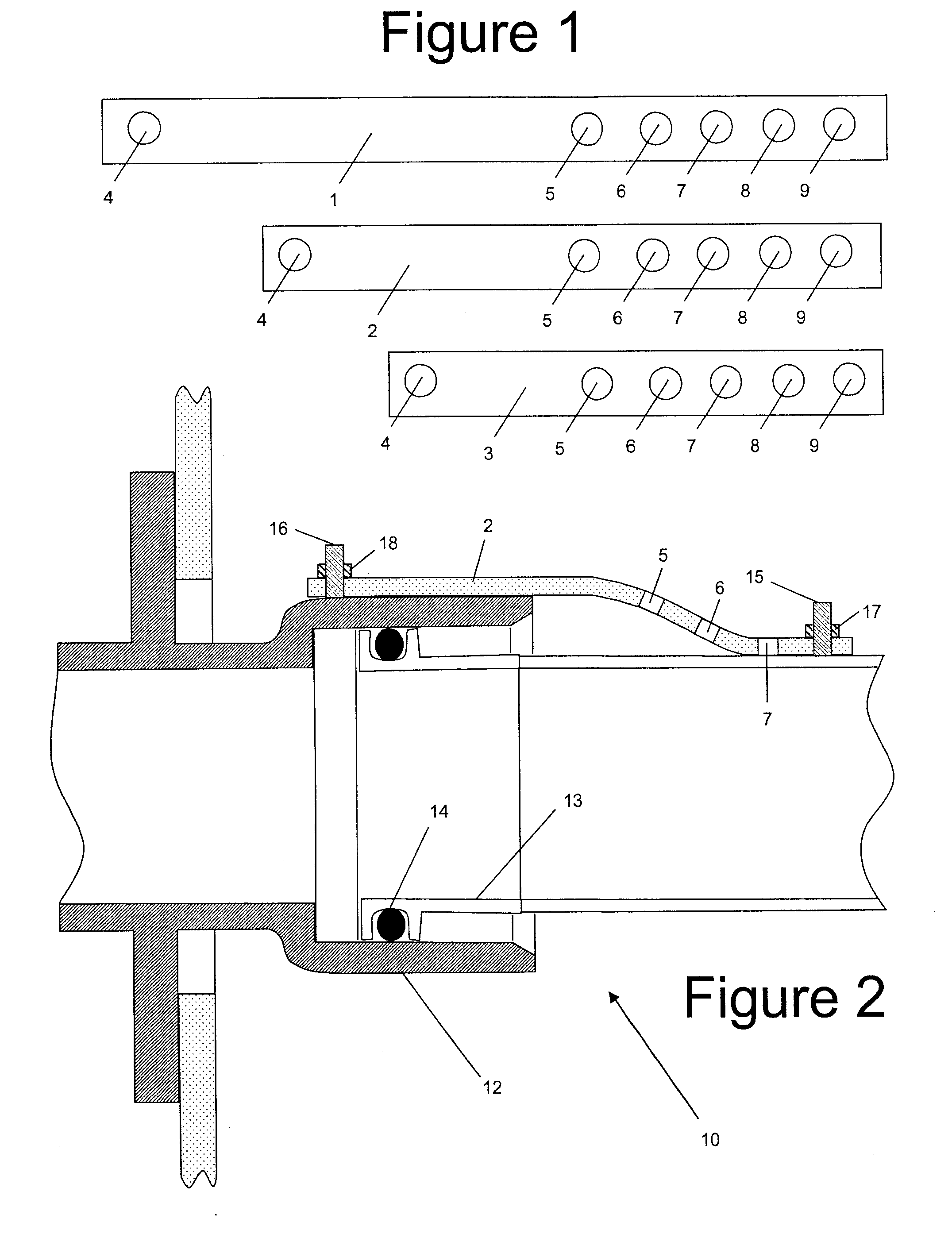
[0034]FIG. 1 shows a kit of parts comprising three bonding leads 1-3. Each bonding lead comprises a conductive elastomer: that is, an elastomer loaded with conductive filler. One suitable filler material would be a fluorosilicone loaded with carbon black particles or carbon nanotubes.

[0035]The elastomer is reinforced by a fabric element (not shown). This fabric may be formed from a conductive material if desired to increase the electrical conductivity of the bonding lead. This may be necessary for longer lengths of bonding leads.

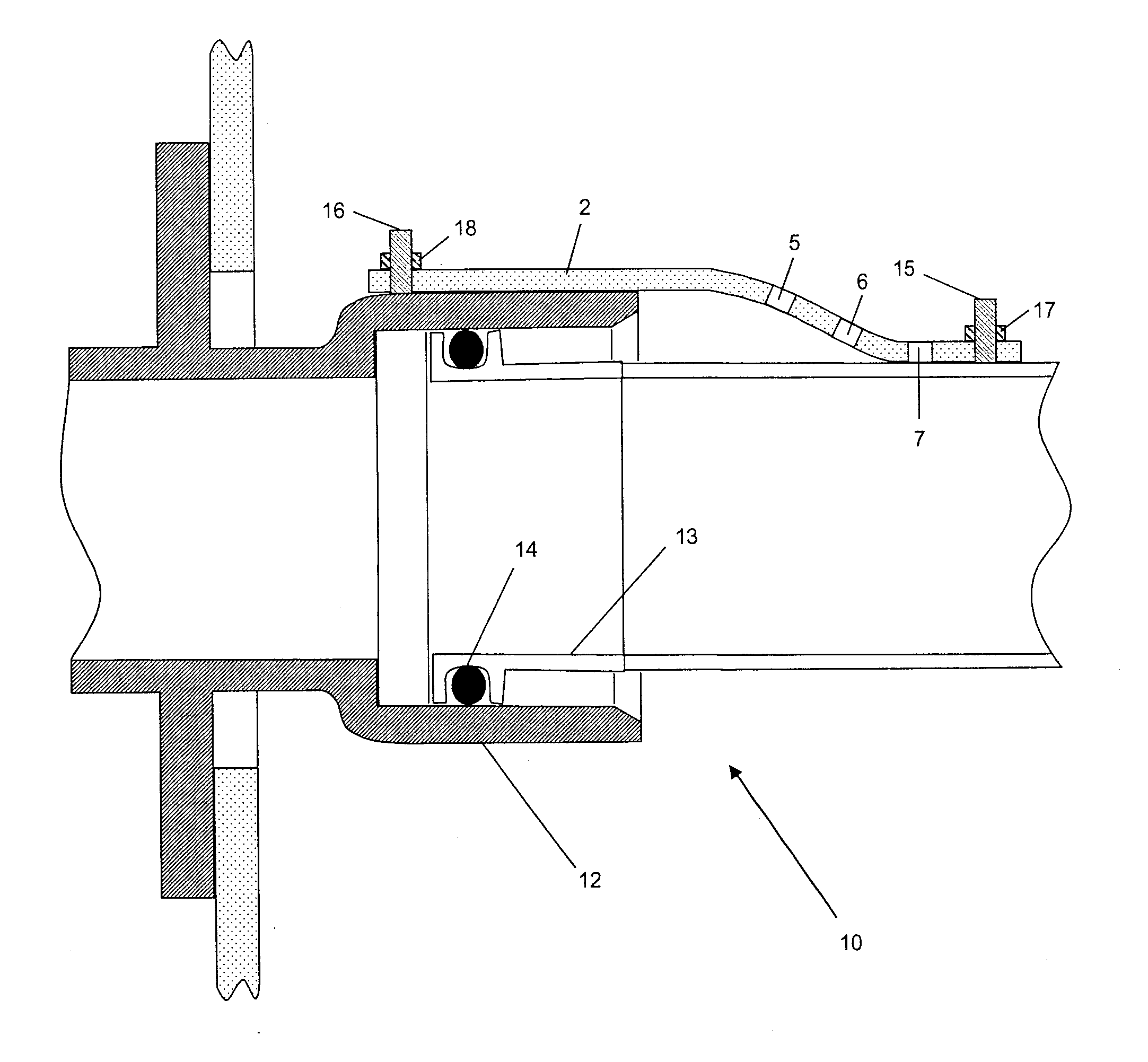
[0036]Each bonding lead is pre-cut with a first attachment hole 4 at one end, and a set of five attachment holes 5-9 in a line at the other end. The leads 1-3 have different lengths which can be selected in accordance with the geometry of the joint. Also, one of the attachment holes 5-9 can be selected as required. Thus for example the attachment hole 5 can be selected to give a minimum length (and hence minimum resistance) or the hole 9 selected to give a ...


PUM


Abstract

A joint on an aircraft, the joint comprising: a first component; a second component joined to the first component; and a bonding lead which forms an electrical connection between the components with a resistance between 100 kΩ and 10 MΩ. Surprisingly, it has been found that a bonding lead with a relatively high resistance can be used without seriously compromising the static discharge performance of the bonding lead, and that the resulting comparatively low flow of current reduces the risk of sparking in the event of an lightning strike. Bonding leads may be provided as a kit of parts in which at least two of the bonding leads have different lengths and the longer lead is formed from a material having a higher bulk conductivity than the shorter lead. Thus the bonding leads can be made with approximately similar resistances regardless of their lengths.

Description

FIELD OF THE INVENTION[0001]The present invention relates to an aircraft joint, a bonding lead for use in such a joint, a method of preventing sparking across such a joint, and a kit of parts comprising two or more bonding leads.BACKGROUND OF THE INVENTION[0002]There is a risk in aircraft fuel systems of a build up of static electricity on one component in comparison to another component to which it is connected. In the prior art, a so-called bonding lead is connected to each side of the joint in order to electrically connect the components and prevent static build up. An example of such a bonding lead is described in the prior art section of US2008 / 0078880.[0003]Bonding leads are traditionally made of highly conductive materials in different forms. These satisfy equipotential and electrostatic discharge requirements but allow the flow of lightning current across the joint. There is a risk that a break in such a bonding lead can result in intermittent contact and a source of sparkin...

Claims


Application Information

Patent Timeline
IPC IPC(8): H05F3/00
CPCH01R4/643F16L25/01H01R13/648B64D37/005Y02T50/40
Inventor WEST, COLIN JOHNSUTTON, DAVID ALISTAIRMALIA, ROBERT BERNARDMILLS, RICHARD EDWARDPOUT, ALAN DONALD
Owner AIRBUS OPERATIONS LTD
Why Eureka
Try Eureka