
Securing structure of sensor element having lead and securing unit thereof

a technology of securing structure and sensor element, which is applied in the direction of positive temperature coefficient thermistors, instruments, heat measurement, etc., can solve the problems of deteriorating electric characteristics of reactors, overheating of coils, and it is almost impossible to directly secure the sensor element connected to the head portion of the lead

Active Publication Date: 2010-09-09
TAMURA KK
View PDF9 Cites 21 Cited by
  • Summary
  • Abstract
  • Description
  • Claims
  • Application Information

AI Technical Summary

Benefits of technology

[0007]It is therefore an object of the present invention to provide a securing structure and a securing unit for precisely positioning and securing a measuring member having a sensor element and a lead elongated from the sensor element to a subject to be measured.
[0008]It is yet another object of the present invention to provide a non-complicated securing structure which is capable of not only being readily designed and readily attached to a compact and thin-sized reactor but also being fabricated at a low cost and which is further capable of precisely positioning and securing a measuring member having a sensor element and a lead elongated from the sensor element to the compact and thin-sized reactor, when particularly applied to the compact and thin-sized reactor as a subject to be measured.

Problems solved by technology

If high current has been continuously applied to a reactor thus mentioned, the coil comes to be overheated and an electric characteristic of the reactor is thereby deteriorated.
However, it is almost impossible that the sensor element connected to a head portion of a lead is directly secured at the measured point within each reactor.
Under the circumstances, it is difficult that the sensor elements are precisely positioned at the same points within the reactors, respectively.
This causes a much cost up of members for measuring temperature of the reactor.
However, in fact, no effective proposal has been made about a technique for precisely positioning and securing the sensor element connected to the head portion of the lead within the reactor in spite of a compact configuration by the no use of the securing structure with the screw thus mentioned.

Method used


Image

  • Securing structure of sensor element having lead and securing unit thereof
  • Securing structure of sensor element having lead and securing unit thereof
  • Securing structure of sensor element having lead and securing unit thereof

Examples


first embodiment

[0046]Now, referring to FIGS. 1 through 7, description is made about a securing structure for securing a measuring member having a sensor element and a lead elongated from the sensor element to a subject to be measured according to the present invention. In this embodiment, the present invention is applied to a case that a thermistor, as a measuring member, is secured to a reactor, as a subject to be measured.

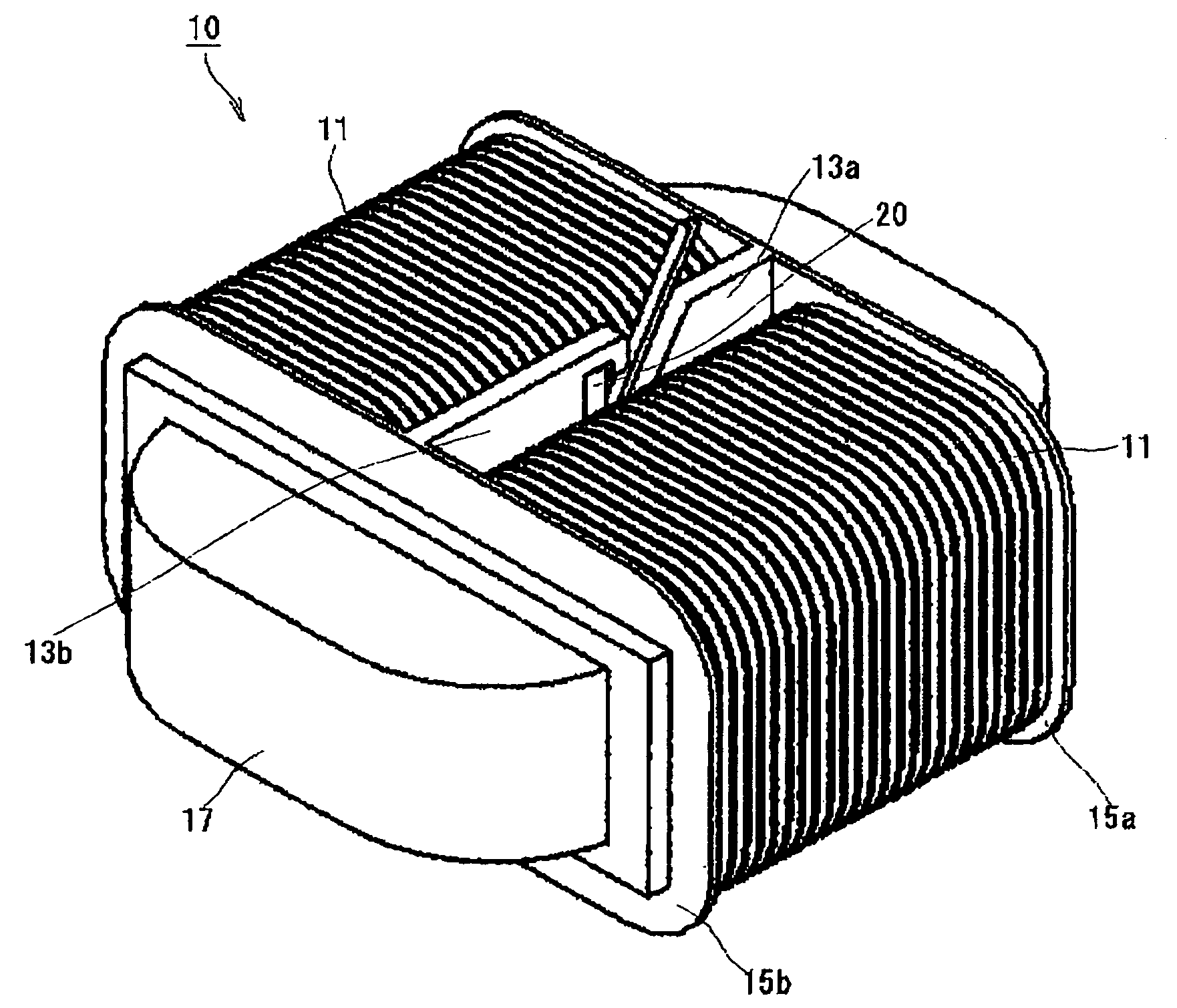
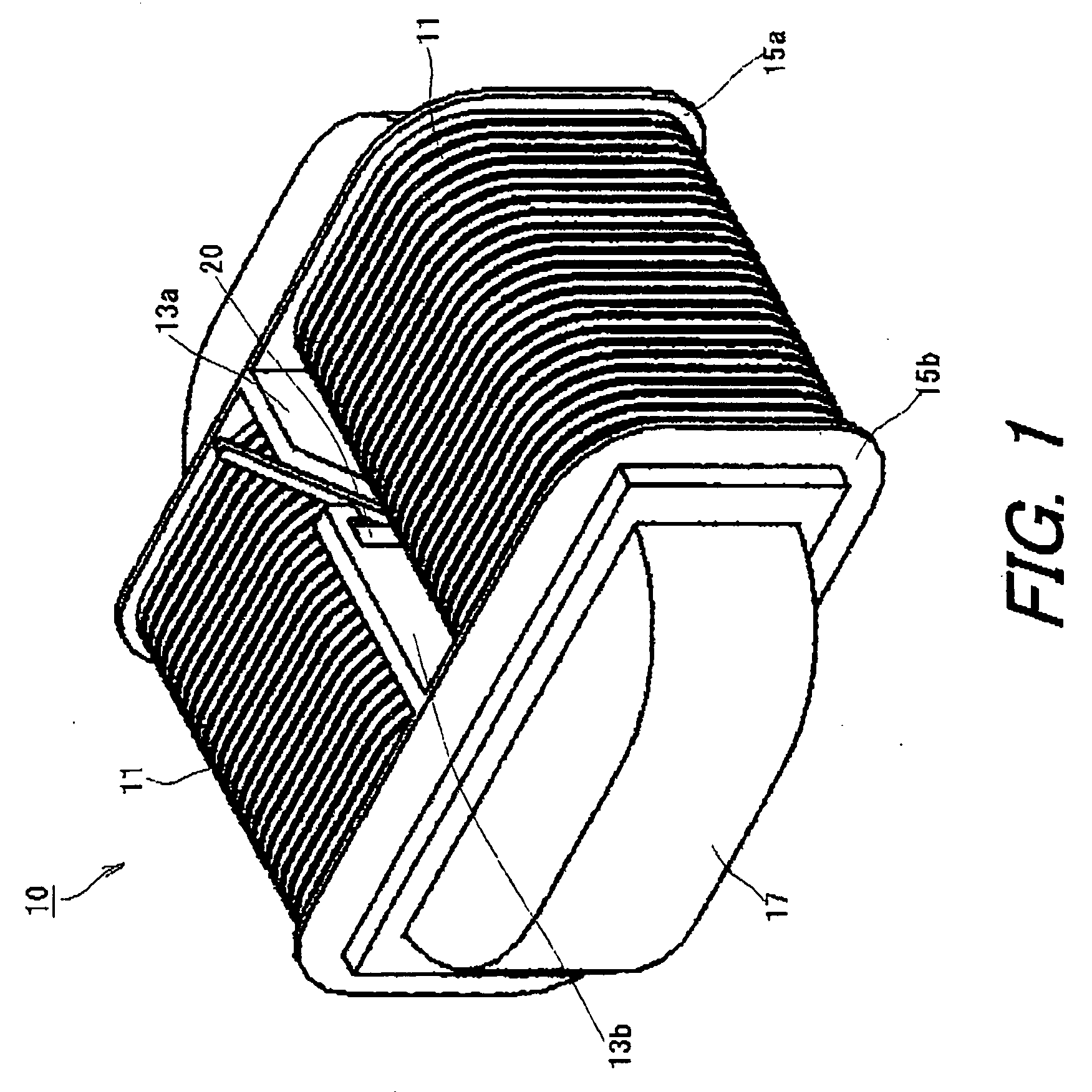
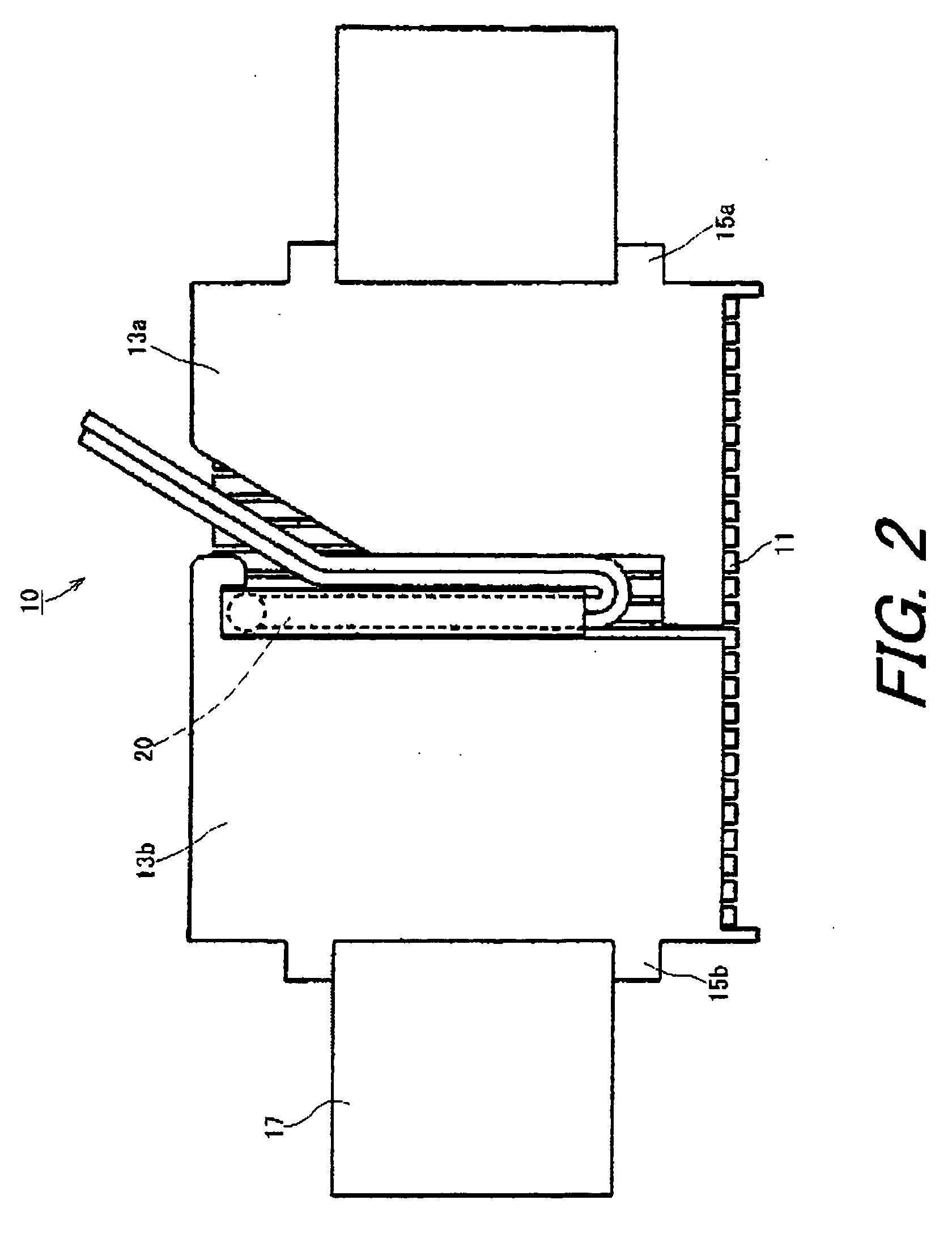
[0047]FIG. 1 is a perspective view for schematically showing a reactor to which a securing structure according to the first embodiment of the present invention is applied. FIG. 2 is a cross sectional view for schematically showing the reactor illustrated in FIG. 1 at a distribution plate of the reactor.

[0048]The reactor 10 is such a reactor used in an electric circuit of an apparatus having compulsory cooling means. As illustrated in FIG. 1, the reactor 10 includes a reactor coil 11, bobbins 15a and 15b having coil distribution plates 13a and 13b formed integrally with the bobb...

fifth embodiment

[0081]As illustrated in FIG. 11, since the securing structure is applied to the more thin-sized reactor 10, the container section 42 is set almost horizontally.

[0082]The insertion section 41 is formed from a left and upper end portion of the coil distribution portion 14a to a substantially center portion thereof. In other words, the left and upper end portion of the coil distribution portion 14a is notched to have a notched portion of a triangle shape that forms the insertion section 41. The container section 42 is formed in a right and lower end portion of the coil distribution portion 14a and most portions of a lower side of the coil distribution portion 14b, as illustrated in FIG. 11. In other words, the coil distribution portion 14a is notched to have another notched portion of a triangle shape. Further, the most portions of a lower side of the coil distribution portion 14b are also notched to have yet another notched portion of a triangle shape. A portion surrounded by these n...

fourth embodiment

[0088]Under the circumstances, the inventors of the present invention have studied various securing structures capable of stable incorporating operations, of reducing the cost for the die, and of reducing the number of processes of design, even if the reactor itself is made compact and thin-sized and thereby the space for disposing the thermistor cannot be obtained sufficiently. Consequently, the inventors of the present invention have invented a securing structure according to the present invention having bobbin configuration illustrated in FIG. 10. Besides, in this embodiment, the thermistor 20 as a measuring member secured to the coil distribution portions 14a and 14b of the bobbins as a subject to be measured is similar to that illustrated in FIG. 3.

[0089]Now, referring to FIG. 10 with reference to FIG. 3 continued, detailed description will be made about the securing structure for securing a sensor element having a lead according to the fourth embodiment of the present inventio...


PUM


Abstract

A securing structure for securing a measuring member having a sensor element and a lead elongated from the sensor element to a subject to be measured, the securing structure includes the measuring member including a measuring section having a covered portion in which a part of the lead elongated from the sensor element and having a predetermined length is covered by a material having a rigidity larger than that of the lead, the covered portion being folded toward the side of the lead elongated from the covered portion to produce a folded end portion; and the subject to be measured having an insertion section through which the measuring section is inserted from the side of the folded end portion, a container section which contains the measuring section inserted through the insertion section, and a contact section with which the head portion of the covered portion comes into contact and by which the measuring section is prevented from falling out, when the lead is pulled.

Description

BACKGROUND OF THE INVENTION [0001]The present invention relates to a securing structure and a securing unit for securing a measuring member, which has a sensor element and a lead elongated from the sensor element, to a subject to be measured, in particular to a securing structure and a securing unit suitable for securing a thermistor to a reactor.[0002]In general, a reactor has, for example, a winding and a core made of a magnetic substance and the winding is wound around the core to make up the coil of the reactor, which enables inductance to be obtained. Conventionally, the reactor is used in a voltage boosting circuit, inverter circuit, active filter circuit, or the like, and, in many cases, such the reactor has a structure in which the core and the coil wound around the core are housed, together with other insulating members or the like in a case made of metal or the like. Japanese Patent Application Laid-open No. 2003-124039 discloses an example of such a reactor.[0003]For a re...

Claims


Application Information

Patent Timeline
IPC IPC(8): G01K1/14
CPCH01F2027/406H01F27/402
Inventor MAENO, KENSUKEHASU, MASATOSHISUZUKI, KOUTAROUNAKATSU, RYO
Owner TAMURA KK
Learn More