
Multicathode x-ray tube

a multi-cathode, x-ray tube technology, applied in the direction of x-ray tube multi-cathode assembly, electrical discharge tube, x-ray tube, etc., can solve problems such as problematic feedthroughs, and achieve the effect of reducing the number of vacuum feedthroughs for the cathode control voltage lin

Active Publication Date: 2010-09-09
SIEMENS HEALTHCARE GMBH
View PDF1 Cites 15 Cited by
  • Summary
  • Abstract
  • Description
  • Claims
  • Application Information

AI Technical Summary

Benefits of technology

The present invention provides an x-ray tube with a plurality of cathodes and several wirelessly activatable elements. The wirelessly activatable elements make electrically conducting connections of the corresponding cathodes when activated by a control signal. The number of vacuum feedthroughs for the control lines of the cathodes is reduced, and power can be fed to the cathodes using a single or a few control voltage lines. The intensity of the current flowing through the electrically conducting connections can be controlled using modulated control signals. A measurement device can be used to measure the current flowing through the control voltage lines, and a calibration mode or a learn mode can be implemented to determine the corresponding control signals for each cathode current measurement value.

Problems solved by technology

It is disadvantageous that for each cathode, which is arranged in the region of the tube under vacuum, a feedthrough toward the outside to a control unit is provided.
The feedthroughs are problematic because the feedthroughs have a high withstand voltage.

Method used


Image

  • Multicathode x-ray tube
  • Multicathode x-ray tube
  • Multicathode x-ray tube

Examples


Embodiment Construction

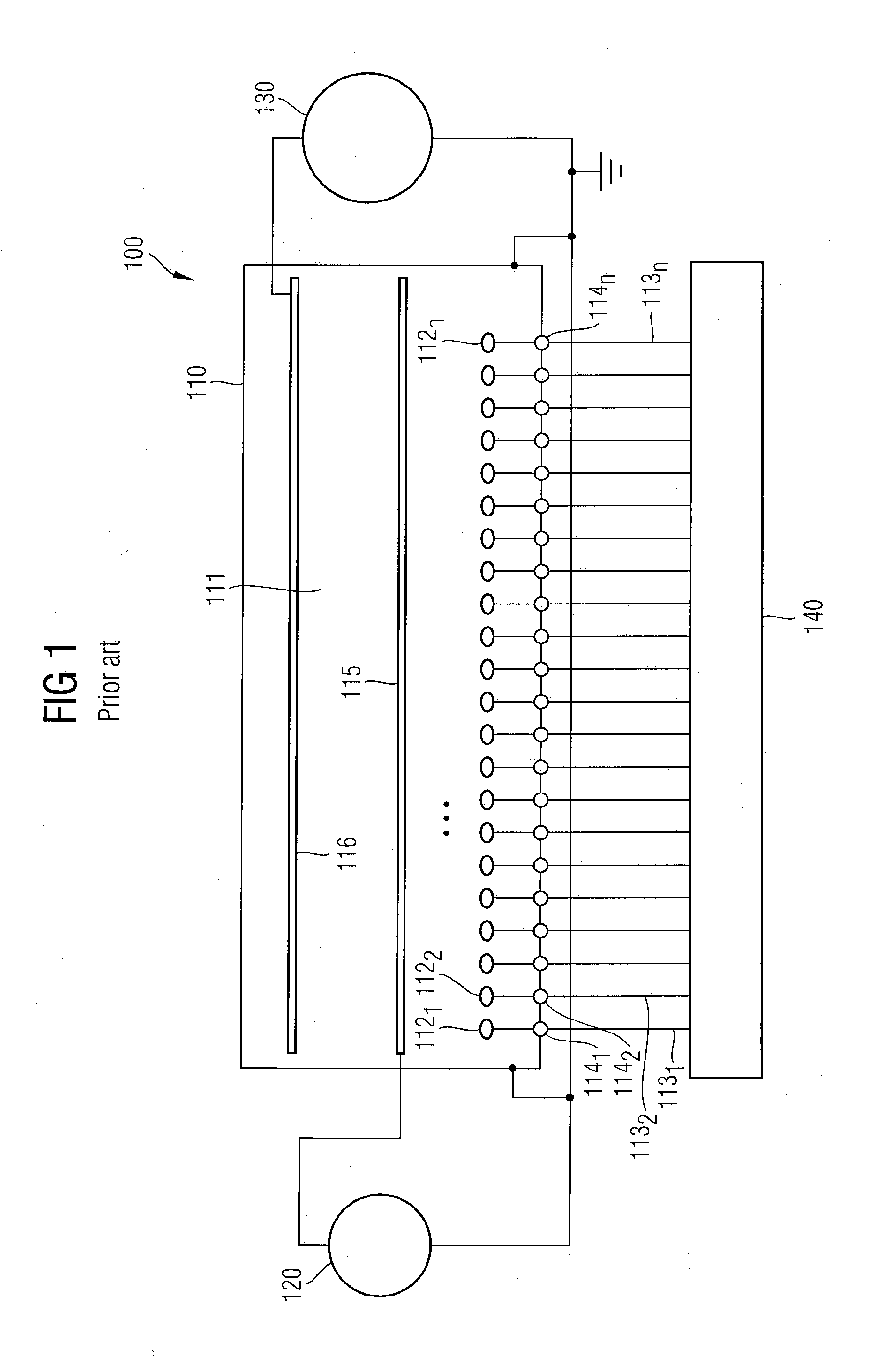
[0020]In FIG. 1, an x-ray tube 110, known from the prior art, with a plurality n of CNT cathodes 1121 . . . 112n in a region under vacuum 111 is schematically shown. Each of the CNT cathodes 1121 . . . 112n is supplied by a separate cathode line 1131 . . . 113n, which is fed into the region under vacuum 111 by a respective vacuum feedthrough 1141 . . . 114n. A grid 115 and an anode 116 are arranged in the region under vacuum 111.

[0021]Additional components of a system 100, in which the x-ray tube 110 is embedded, are located outside of the region under vacuum 111. A grid voltage supply 120 is electrically connected to the grid 115, and an anode voltage supply 130 is electrically connected to the anode 116 and a control unit 140. Typical grid voltages are 5 kV, and typical anode voltages are between 20 kV and 180 kV.

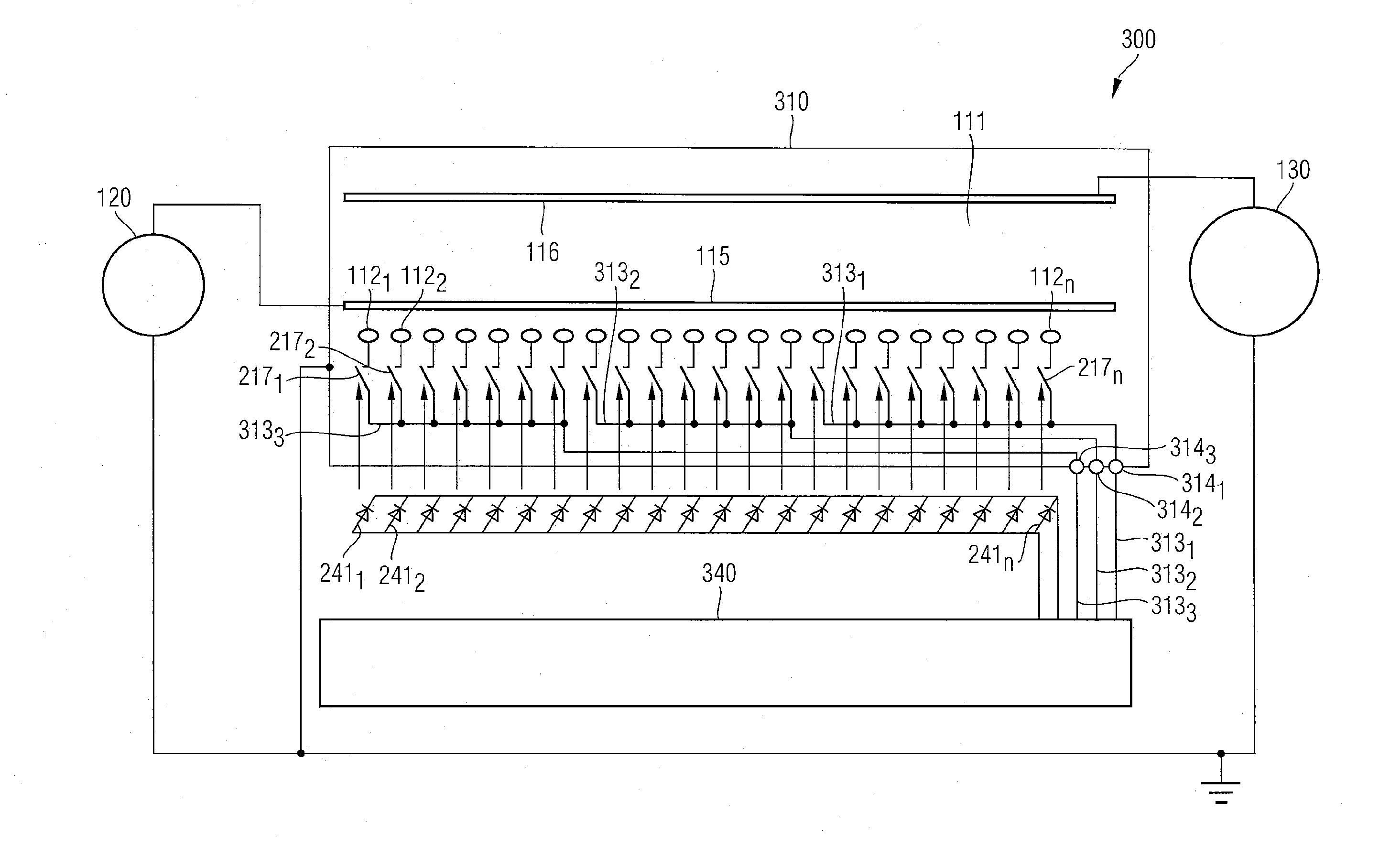
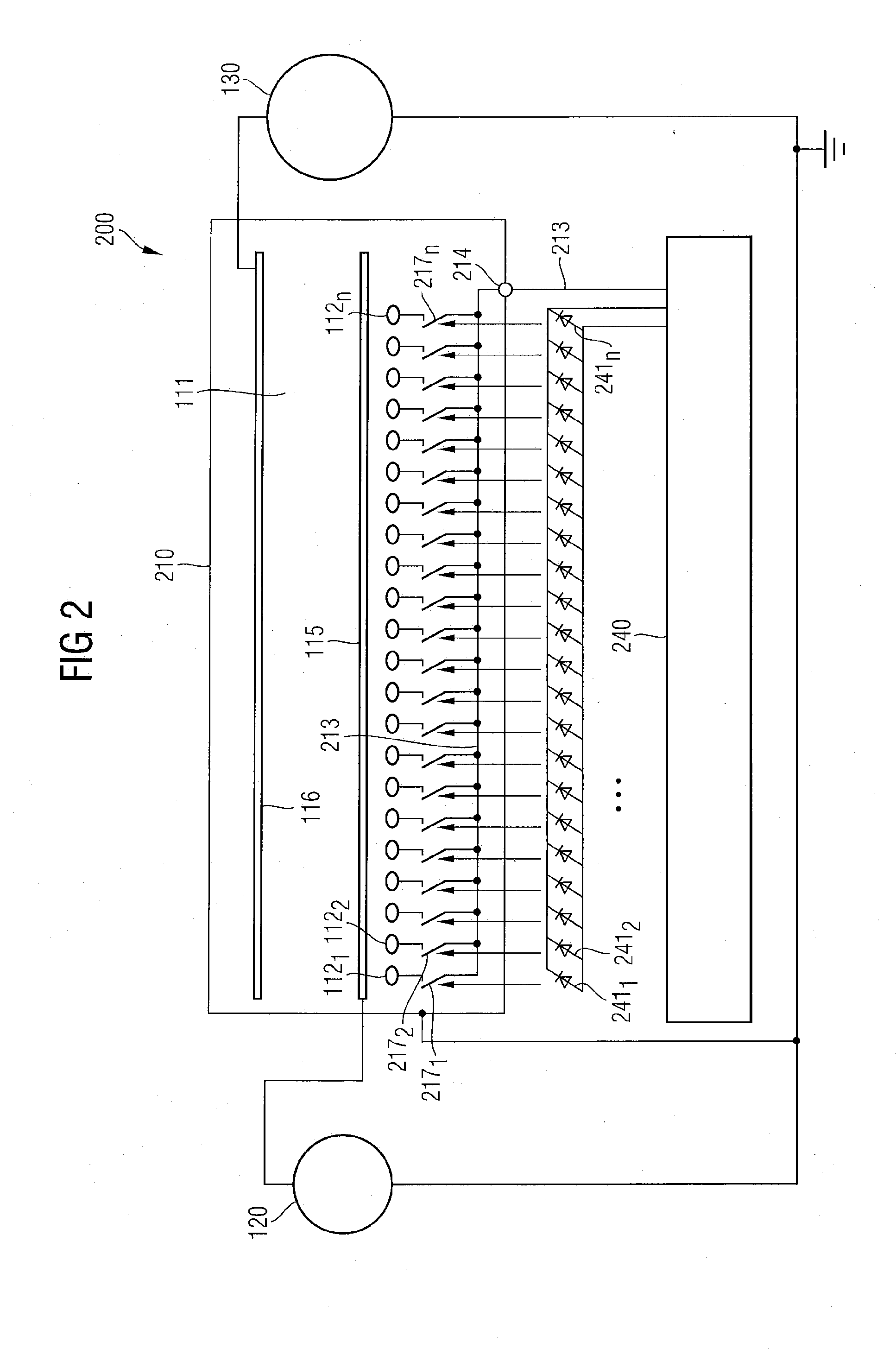
[0022]FIG. 2 schematically shows one embodiment of an x-ray tube 210 integrated in a system 200. The x-ray tube 210 includes a region under vacuum 111, in which a number ...


PUM


Abstract

An improved x-ray tube that includes a plurality of cathodes in a region under vacuum is provided. Several wirelessly activatable elements, which are each assigned to a cathode or a group of cathodes, are arranged in the region under vacuum and make an electrically conducting connection of the cathode or the group of cathodes to a cathode control voltage line when receiving a control signal from outside of the region under vacuum. A system that includes the improved x-ray tube and several transmitter elements for the wireless activation of the wirelessly activatable elements is also provided.

Description

[0001]The present patent document claims the benefit of DE 10 2009 011 642.7, filed Mar. 4, 2009, which is hereby incorporated by reference.BACKGROUND[0002]The present embodiments relate to an improved x-ray tube with several cathodes.[0003]It is known in the prior art to replace conventional thermal cathodes in x-ray tubes with carbon nanotubes (CNT). CNTs can be embodied in such a way that the CNTs emit electrons by field emission and serve as efficient electron emitters for flat and self-luminous field emission displays or as cathodes in x-ray tubes.[0004]In one known embodiment of an x-ray tube, several CNT cathodes are arranged in a tube (see Zhang, J., et al., “Stationary scanning x-ray source based on carbon nanotube field emitters.” Appl. Phys. Lett. 86, 18104 (2005)). Such a multicathode tube allows a spatial resolution, which can only be achieved with conventional single cathode tubes by mechanical displacement of the x-ray tube.[0005]In the field of computed tomography (C...

Claims


Application Information

Patent Timeline
Patent Type & Authority Applications(United States)
IPC IPC(8): H01J35/06
CPCH01J35/065H01J2235/068H01J2235/062H01J2235/0236
Inventor BEYERLEIN, WALTERBOHME, ANDREASHEMMERLEIN, MARKUSHEUERMANN, OLIVEROELSCHLEGEL, JURGENWEHRLE, PETER
Owner SIEMENS HEALTHCARE GMBH
Learn More