Tissue measurement and ablation antenna

Inactive Publication Date: 2010-09-09
MEDICAL DEVICE INNOVATIONS
View PDF2 Cites 89 Cited by
  • Summary
  • Abstract
  • Description
  • Claims
  • Application Information

AI Technical Summary

Benefits of technology

[0004]The present invention may provide an antenna that can contribute to the impedance matching of the electrosurgical systems described in WO 2004/047659 and WO 2005/115235, and that can preferably operate efficientl

Problems solved by technology

Conventional antenna structures can be

Method used


Image

  • Tissue measurement and ablation antenna
  • Tissue measurement and ablation antenna
  • Tissue measurement and ablation antenna

Examples


Embodiment Construction

; FURTHER OPTIONS AND PREFERENCES

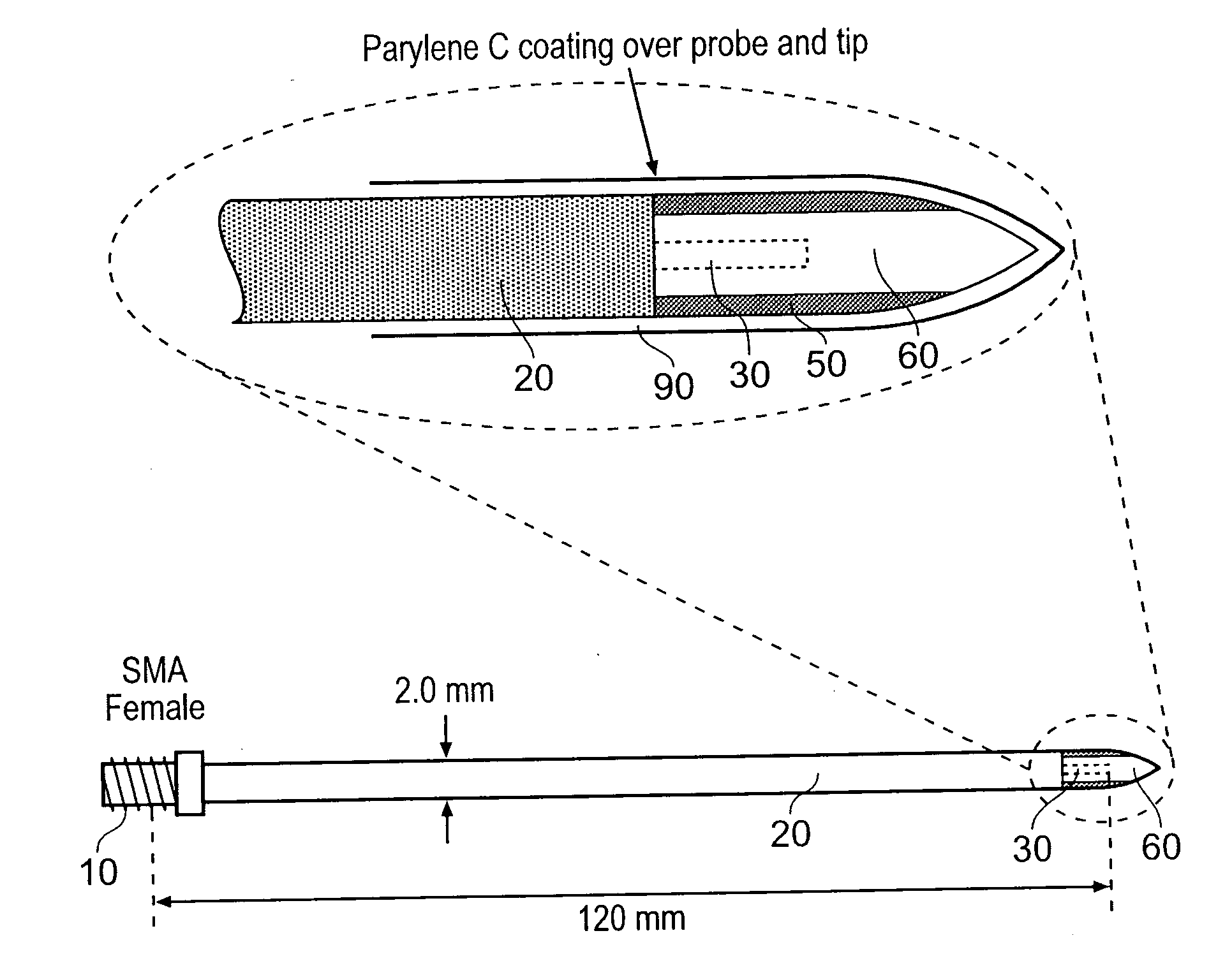
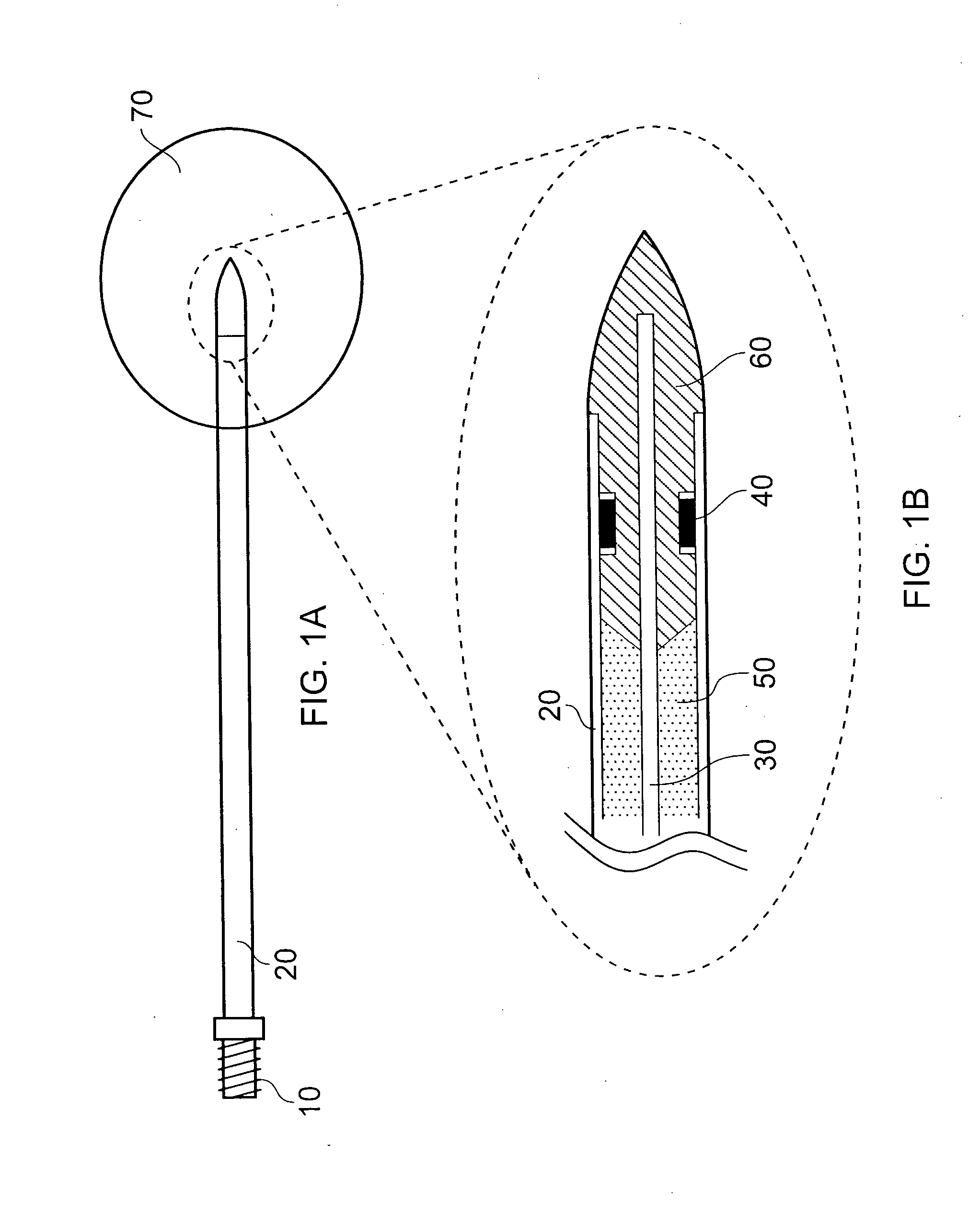
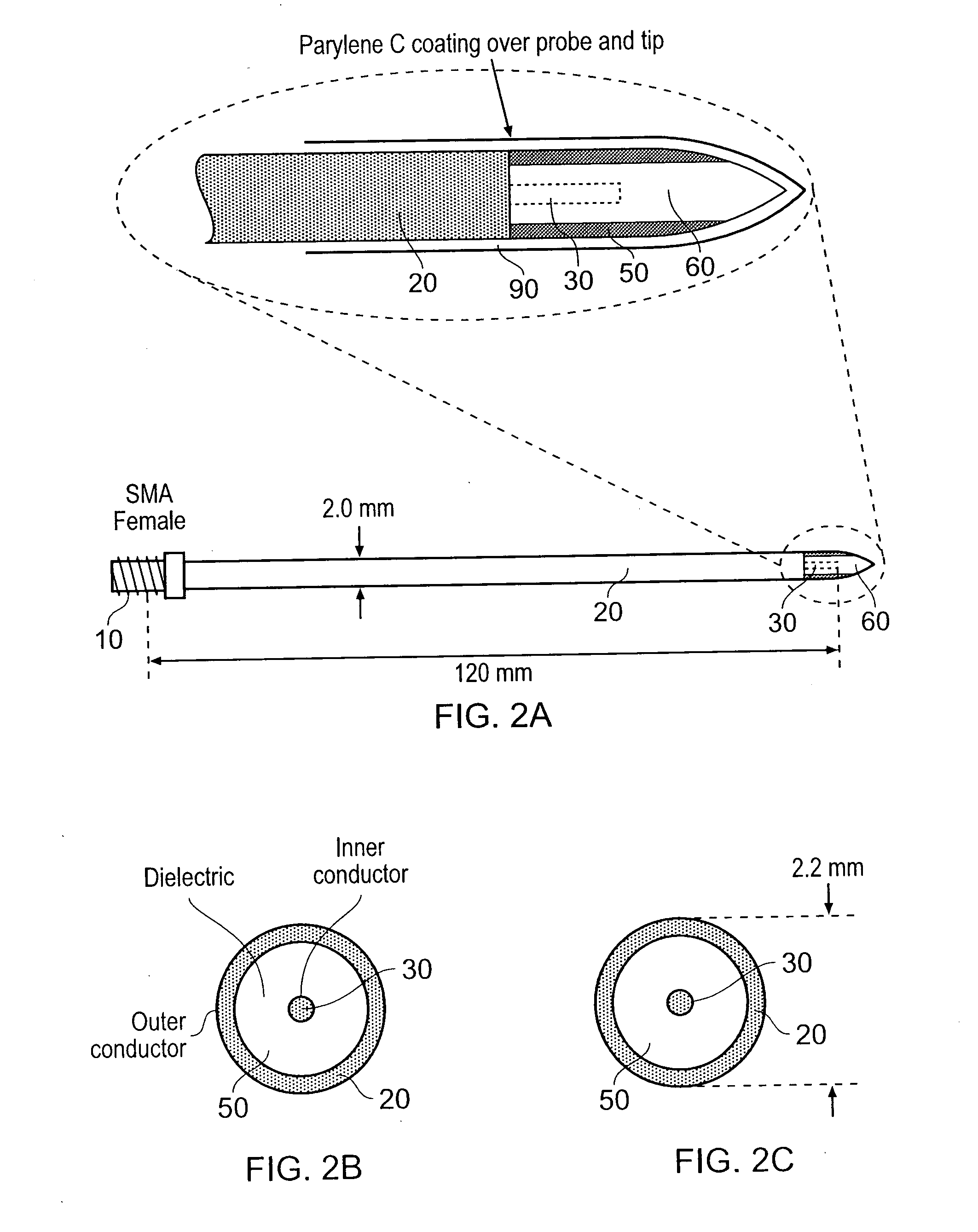
[0040]The description given below focuses on the design and development of the measurement / ablation antenna.

[0041]Details of materials used for practical implementation and means of manufacture are addressed. It is envisaged that the antenna will be a disposable item, hence design for manufacture will become an important feature of the antenna structure.

[0042]The impedance measurements given in this description for the optimised antenna structure are measured by attaching a measurement port to the proximal end of the antenna structure and the distal tip end fully immersed in a block of biological tissue that is described by a value of relative permittivity and conductivity (dielectric materials can be described by these two properties). Proximal end measurements are compared for various tissue types. Values of relative permittivity and conductivity for biological tissues used in the simulations presented here were obtained from the following referenc...


PUM


Abstract

A surgical antenna for radiating microwave energy (e.g. frequency 500 MHz to 60 GHz) from a e.g. ceramic insertion tip (60) into biological tissue is disclosed. The tip is provided at the end of an elongate body which delivers the microwave energy to the tip via an inner conductor (30), an outer conductor (20) surrounding the inner conductor and a dielectric material (50) therebetween. The impedance of the insertion tip (60) is selected to improve impedance matching with the complex conjugate of the complex impedance of the tissue at a treatment frequency. For example the insertion tip may act as or include at least one quarter wavelength impedance transformer. By closely matching the antenna's impedance to the tissue, dynamic tuning (if used) can be performed much more efficiently. Impedance matching at the tip can also focus the radiated energy distribution.

Description

TECHNICAL FIELD[0001]The present invention relates to a surgical antenna for delivering microwave energy into biological tissue. For example, surgical antennas are used to perform controlled and focussed ablation of cancerous tumours. Alternatively or additionally, such antennas can measure information concerning the structure of biological tissue e.g. in order to differentiate between tissue types, and / or to identify various types of cancerous tumours, and / or to differentiate between healthy tissue and cancerous tissue, and / or to determine the stage of tumour growth, and / or to provide information to control associated electronic instrumentation to enable the distal end of the antenna to be impedance matched with the complex impedance of the biological tissue in order to enable maximum power transfer between an energy source (or the distal tip of the antenna) and the biological tissue being treated.BACKGROUND TO THE INVENTION[0002]WO 2004 / 047659 and WO 2005 / 115235 relate to apparatu...

Claims


Application Information

Patent Timeline
IPC IPC(8): A61B18/18
CPCA61B18/1815A61B18/18
Inventor HANCOCK, CHRISTOPHER P.WHITE, MALCOLM
Owner MEDICAL DEVICE INNOVATIONS
Why Eureka
Try Eureka