Flush patch for elastomeric implant shell

a technology of elastomeric implants and flushing, which is applied in the field of flushing patches of elastomeric implants, can solve problems such as irritation of tissue in contact with the exterior of implants

Inactive Publication Date: 2010-09-09
ALLERGAN INC
View PDF33 Cites 22 Cited by
  • Summary
  • Abstract
  • Description
  • Claims
  • Application Information

AI Technical Summary

Benefits of technology

[0021]The self-sealing channel may comprise a fluid valve with a valve seat fixed within the patch and an elastomeric diaphragm in sealing relationship to the valve seat, and the step of partially filling the hollow shell comprises inserting a hollow fill tube connector into the fluid valve and causing saline to flow through the connector into the hollow shell. In one application of the method, the step of inserting the partially filled hollow shell into the cavity includes rolling or folding the shell so it can be inserted through a small incision. The method may also involve allowing the implant to unfold after insertion of the partially filled hollow shell into the cavity and before the step of adjusting the size of the inserted implant. The step of adjusting the size of the inserted breast implant may include using a syringe to inject saline through the patch channel.

Problems solved by technology

The process also results in a flexible implant shell having a hole that requires a patch.
The overlap of the patch on the shell results in a slight surface step on the inside or outside of the shell which may be noticeable in the finished product, which is undesirable.
Also, such a palpable step or discontinuity may irritate tissue in contact with the exterior of the implant.

Method used


Image

  • Flush patch for elastomeric implant shell
  • Flush patch for elastomeric implant shell
  • Flush patch for elastomeric implant shell

Examples


Embodiment Construction

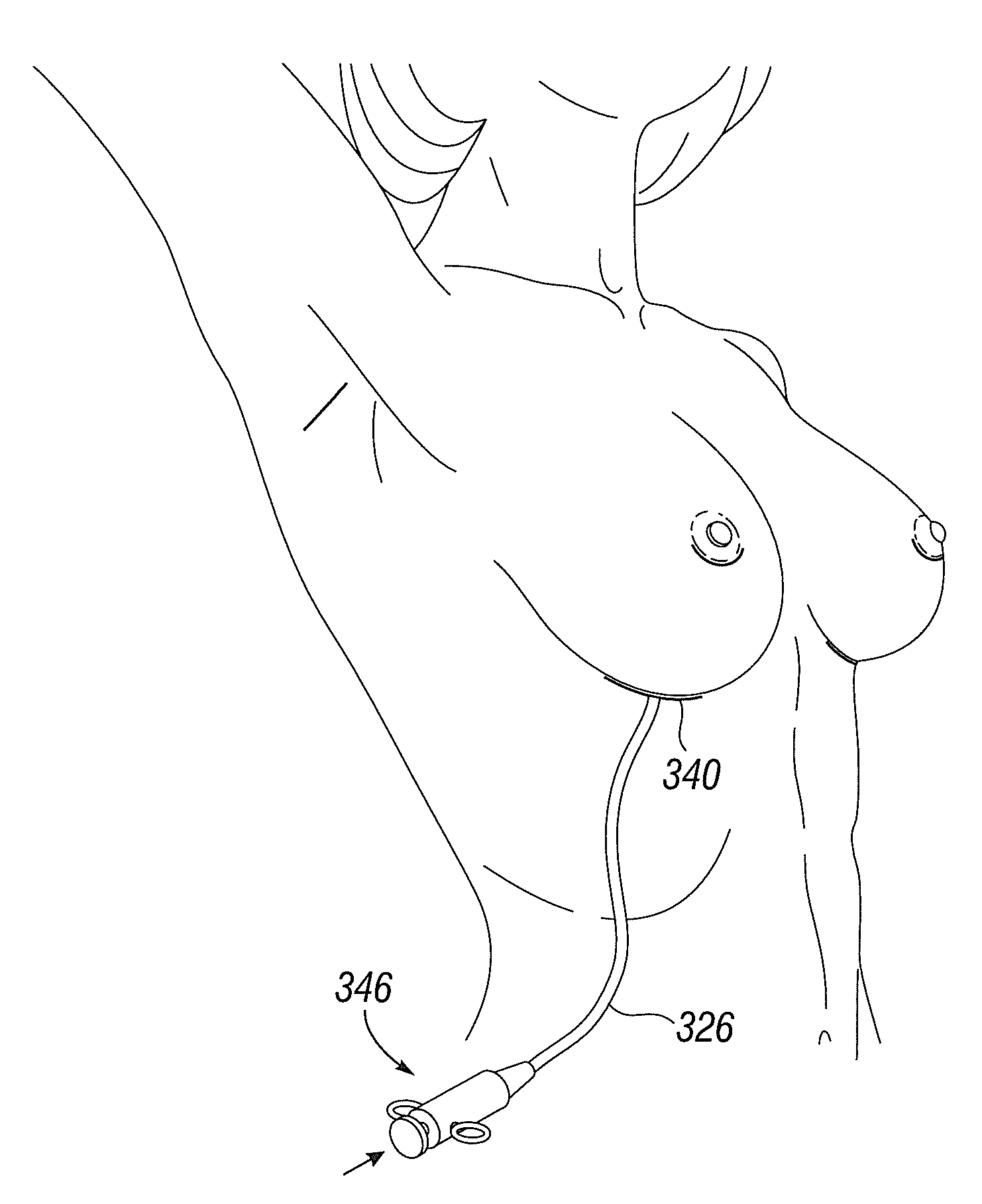
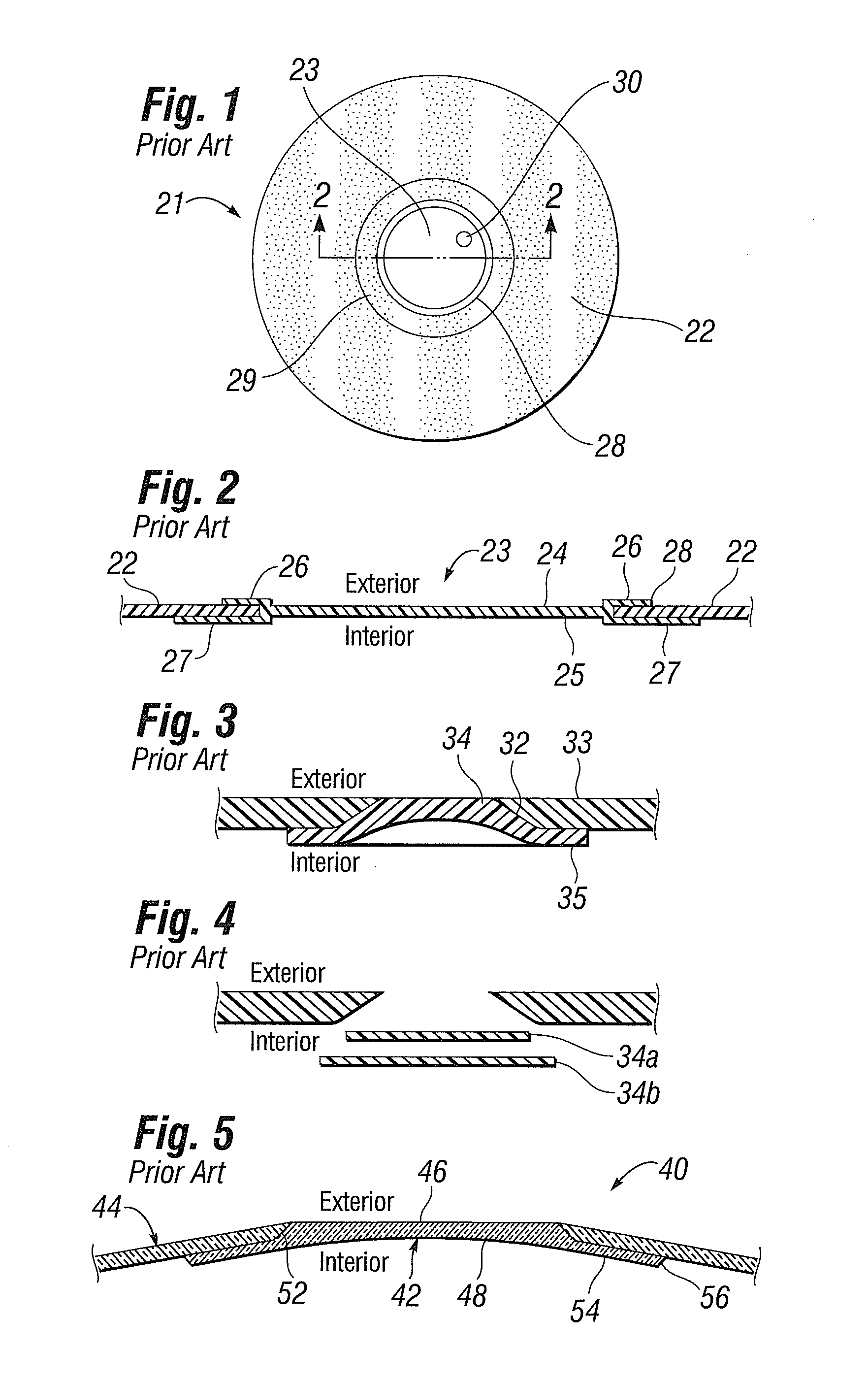
[0047]The present invention provides a gel-filled implant prosthesis incorporating a shell composed partly or entirely of a fluid barrier layer, preferably a silicone elastomer. The implant shells of the present invention may have a single material layer of homogeneous or uniform composition, or a laminated or layered configuration. The primary application for gel-filled soft implants is to reconstruct or augment the female breast. Other potential applications are implants for the buttocks, testes, or calf, among other areas. Moreover, though the present invention is particularly advantageous for gel-filled implants, saline filled breast implants or intragastric balloons may be modified to incorporate the benefits herein. Further, tissue expanders which may not be viewed as implants, per se, may also use the concepts disclosed herein. For that matter, the term implant as used herein refers to long and short-term implanted devices.

[0048]The implant shells of the present invention are...


PUM


Abstract

An elastomeric fluid-filled prosthetic implant having a shell and a patch providing a reinforced access region on the shell for introduction of manufacturing implements, such as a gel-filling tool. The shell may cover the entire inner face of the patch, or a substantial part thereof, and a peripheral edge of the patch and the shell cooperate to form a flush interface with no sudden surface steps on both interior and exterior surfaces of the implant. The removal of any surface steps eliminates undesirable tactile discontinuities and stress points that may cause the shell wall to wear or may irritate the surrounding tissues. The prosthetic implant may be a breast implant formed of a silicone elastomer. The patch may be the same material or a liquid silicone rubber, but at least has similar material properties such as elastic modulus, durometer and elongation. The patch may include a channel, such as a self-sealing channel, used for introducing silicone to the mold to form the shell, for venting the mold cavity during the mold process, and/or for introducing the silicone gel into the hollow prosthesis. The patch may be combined with a fluid fill valve for manually adjusting the amount of a fluid such as saline within the shell after the mold process.

Description

RELATED APPLICATIONS [0001]The present application is a continuation-in-part of U.S. application Ser. No. 12 / 431,070, filed Apr. 28, 2009, which claims priority to U.S. Provisional Patent Application Ser. No. 61 / 038,919 filed Apr. 28, 2008, both of which are incorporated herein by reference.FIELD OF THE INVENTION [0002]The present invention relates to patches for elastomeric implants and, more particularly, to devices and methods for forming a patch flush with an elastomeric implant shell.BACKGROUND OF THE INVENTION[0003]Implantable prostheses are commonly used to replace or augment body tissue. In the case of breast cancer, it is sometimes necessary to remove some or all of the mammary gland and surrounding tissue that creates a void that can be filled with an implantable prosthesis. The implant serves to support surrounding tissue and to maintain the appearance of the body. The restoration of the normal appearance of the body has an extremely beneficial psychological effect on pos...

Claims


Application Information

Patent Timeline
Patent Type & Authority Applications(United States)
IPC IPC(8): A61F2/12
CPCA61F2/12A61F2250/0007A61F5/003A61F2250/001
Inventor SCHUESSLER, DAVID J.
Owner ALLERGAN INC
Why Eureka
Try Eureka