Geographical distributed storage system based on hierarchical peer to peer architecture

a distributed storage and hierarchical technology, applied in the field of distributed storage systems, can solve the problems of not having a central control server or dedicated administrator or highly skilled engineer to maintain the service, becoming much more difficult to design, install, manage and maintain the system, etc., and achieves the effect of being more applicable and feasible to implemen

Inactive Publication Date: 2010-09-09
HITACHI LTD
View PDF4 Cites 108 Cited by
  • Summary
  • Abstract
  • Description
  • Claims
  • Application Information

AI Technical Summary

Benefits of technology

[0015]Regarding to the problem described in US Patent Application Publication No. 20040085329A1, according to the present invention when a new node is connected to the system, an administrator at each location gives a name of an ISP in which a node is located so the system groups the nodes with same ISP name. Because it is not a difficult task for an administrator to know to which ISP the new node is connected, the system can group the nodes accurately compared with using latency information.
[0016]Regarding to the problem described in US Patent Application Publication Nos. 20040249970A1 and 20040054807A1, according to the present inventio

Problems solved by technology

In a case where storage systems are located at multiple geographical locations, it becomes much more difficult to design, install, manage and maintain the system compared with a storage system located in one location.
However, it is too expensive to employee so many engineers and successfully continue the business because customers do not pay a lot for just storing and accessing data.
There is no central control server or dedicated administrator or highly skilled engineer to maintain the service.
Because of this, network bandwidth is not used efficiently.
Networking traffic caused by P2P has been consuming a large part of network bandwidth for

Method used


Image

  • Geographical distributed storage system based on hierarchical peer to peer architecture
  • Geographical distributed storage system based on hierarchical peer to peer architecture
  • Geographical distributed storage system based on hierarchical peer to peer architecture

Examples


Embodiment Construction

[0067]The present invention as will be described in greater detail below provides an apparatus, method and system, particularly, for example, a geographically distributed storage system configured to have a hierarchical P2P architecture system. The present invention provides various embodiments as described below. However it should be noted that the present invention is not limited to the embodiments described herein, but could extend to other embodiments as would be known or as would become known to those skilled in the art.

[0068]The geographically distributed storage system (GDSS) will be described below with respect to the accompanying drawings.

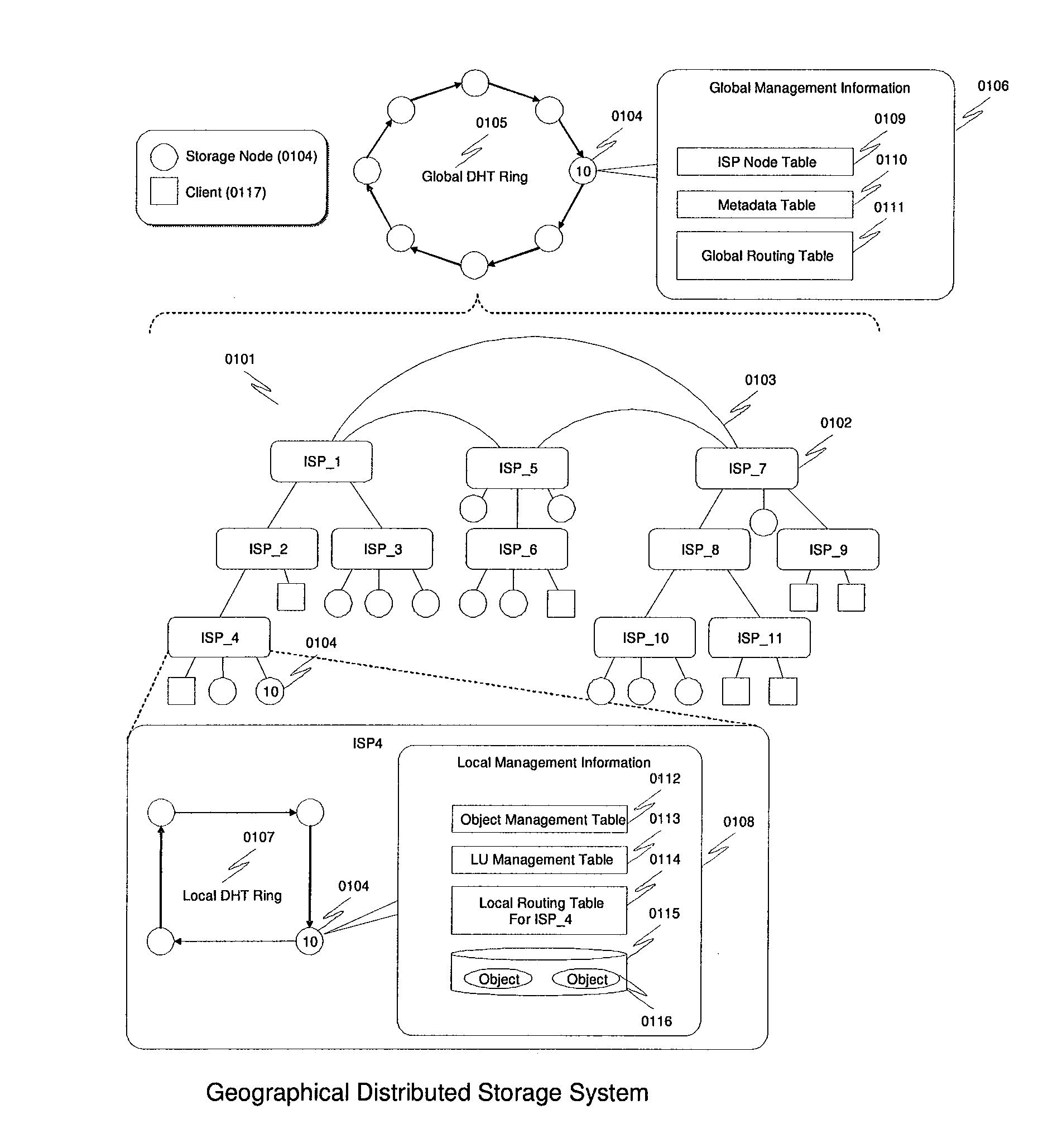
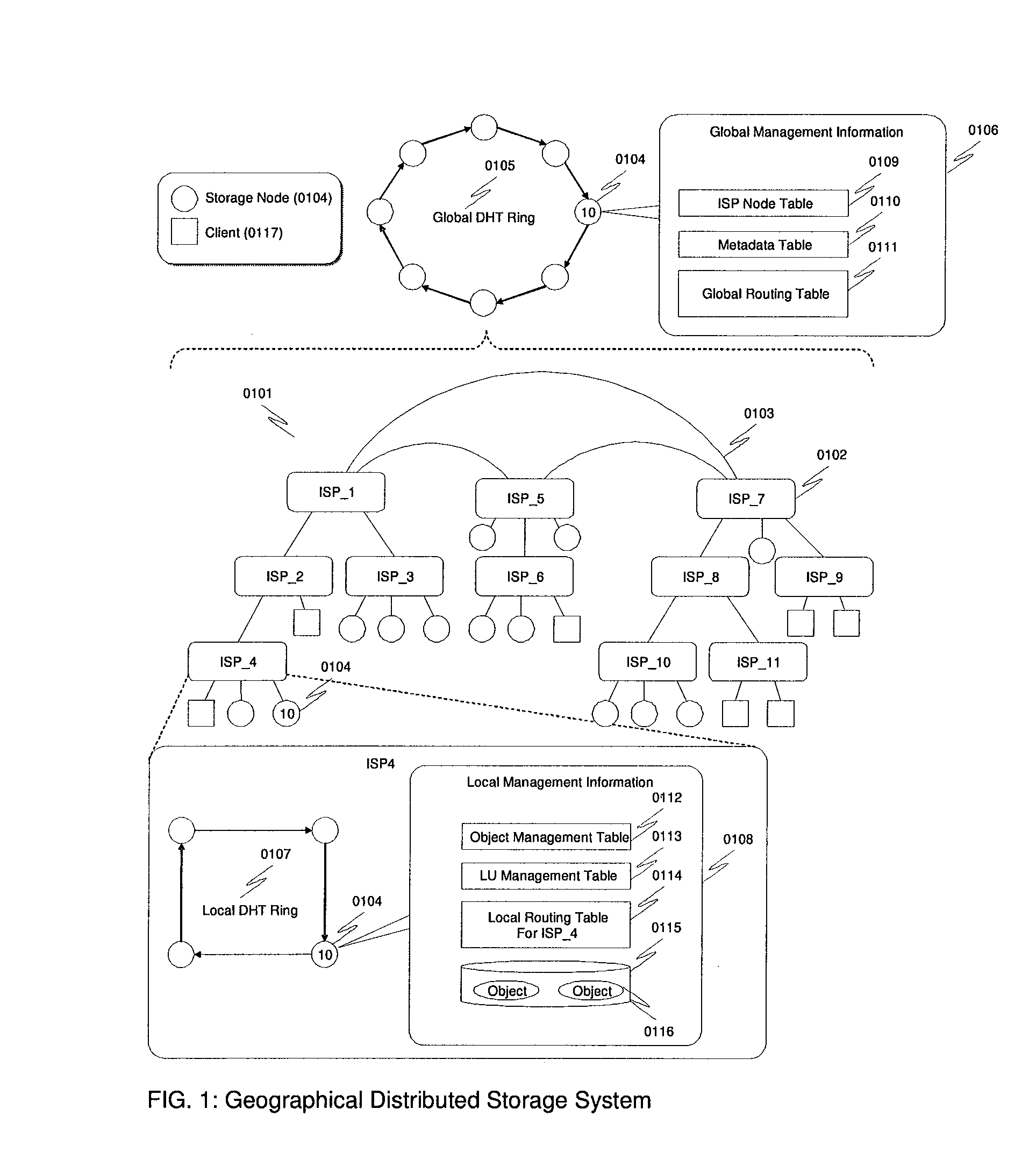
[0069]FIG. 1 shows an overall system diagram for the GDSS 0101. GDSS includes many storage nodes 0104 and each storage node 0104 is connected to one of Internet Service Providers (ISPs) 0102 around the world. ISPs are connected together via a wide area network 0103, thereby forming a part of the wide area network so as to construct the Int...


PUM


Abstract

A geographically distributed storage system including a global Peer-To-Peer (P2P) ring and a local P2P ring. The global P2P ring includes all storage nodes and the local P2P ring includes a group of the storage nodes. Each of the group of storage node belongs to the global P2P ring and the local P2P ring and each storage node includes global and local management information. The global management information includes a node table for managing topology information of a network connecting the group, a metadata table for managing locations of stored data objects, and a global routing table for managing routing in the global P2P ring. The local management information includes an object management table for managing stored data objects in the group, a Logical Unit (LU) management table for managing logical units in the group and a local routing table used for managing routing in the local P2P ring.

Description

BACKGROUND OF THE INVENTION[0001]The present invention relates generally to a distributed storage system. More particularly, the present invention relates to a geographically distributed storage system configured to have a hierarchical peer to peer (P2P) architecture.[0002]In the era of Web Computing, highly scalable storage systems are needed. Such a storage system needs to meet the demands for storing and accessing information, wherein such demands increase exponentially because web services typically start from a small number of users and expand rapidly when the services are known by other users around the world. Due to this characteristic of web computing, such a storage system needs to be scalable from multiple perspectives including performance, capacity, manageability, and so on.[0003]Geographically distributed storage systems are required in order to reduce usages of network bandwidth, reduce response time to access data, increase availability of services, and so on. In a ca...

Claims


Application Information

Patent Timeline
IPC IPC(8): G06F17/30G06F7/00G06F15/16
CPCG06F17/30241H04L41/0893H04L41/12H04L67/1059H04L67/104H04L67/1065H04L45/02G06F16/29
Inventor KODAMALIN, WUJUAN
Owner HITACHI LTD
Why Eureka
Try Eureka