Radiant thermal barrier

Inactive Publication Date: 2010-09-16
LEWIS DAVID L
View PDF4 Cites 12 Cited by
  • Summary
  • Abstract
  • Description
  • Claims
  • Application Information

AI Technical Summary

Benefits of technology

[0007]It is an object of the invention to provide a combination convective/conductive radiant

Problems solved by technology

A problem with this method of installation of a radiant reflective barrier is that it is not easy to judge the proper amount of insertion of the insulation so as to maintain the at least three-quarters to one inch of air space needed to create a proper air cavity between the

Method used


Image

  • Radiant thermal barrier
  • Radiant thermal barrier
  • Radiant thermal barrier

Examples


first embodiment

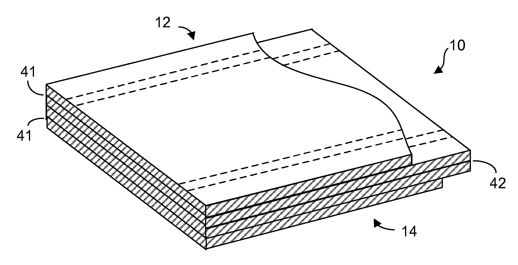
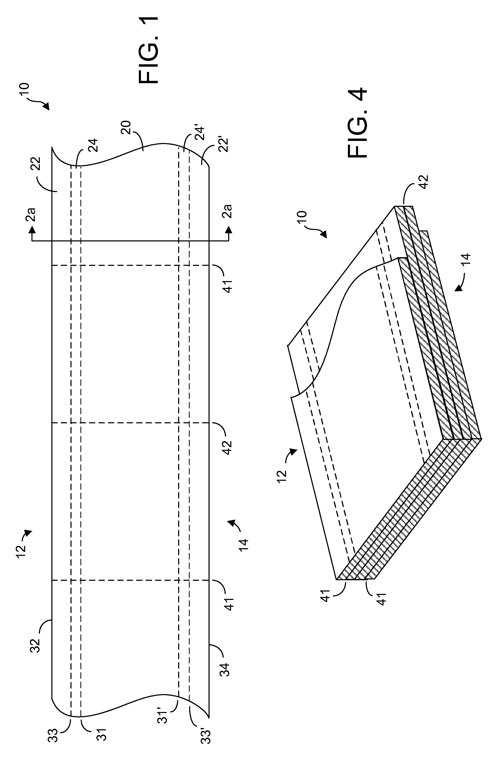
[0027]Turning first to FIG. 1, a radiant heat barrier 10 is shown according to the present invention comprising an extended length of sectional panels 20 such as laminates of a card board or of a synthetic resin foam board such as polystyrene or polyurethane or of any lightweight construction material usually formed into a thin, rectangular panel or board. Laminar skins may be applied on each planar surface thereof to form the laminate board. The laminar skins may be inherent in the material of the panels or board itself. The laminar skins provide rigidity and integrity for the unfolded planar sections of building panels in the unfolded state of FIG. 1 in its extended length. Such skins may be fabricated of synthetic resin film and one or both of the skins may be metalized.

[0028]The radiant thermal barrier 10 shown in its extended length in FIG. 1 is shown with a series of transverse cuts 41, 42 spaced along the extended length. In the production process, alternating cuts 41 may be ...

second embodiment

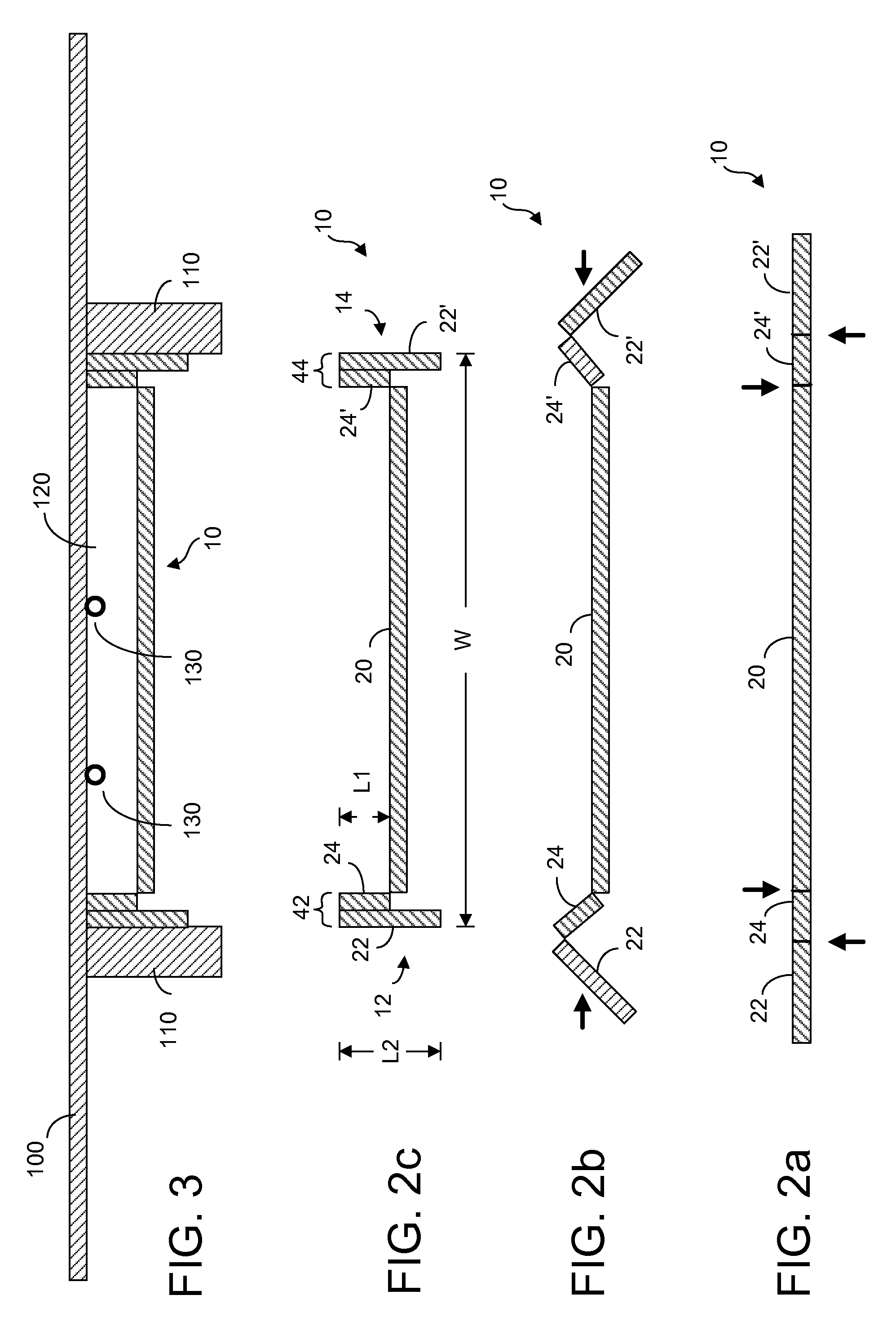
[0039]FIG. 5a shows a sectional view of the extended panel of FIG. 1 before formation of the channel of FIG. 5c using a material with folding lines pressed according to the present invention. Instead of the cuts of FIG. 2a, FIG. 5a shows v-shaped indentations pressed into the material of the board. The board includes a main channel inner part comprising a central part of panel sections 20 between inner folding lines 31, 31′, an inner channel wall section 24, 24′ along an inner edge part of the board and an outer channel wall section 22, 22′ along an outer edge part of the board. As mentioned, the two pairs of longitudinal folding lines 31, 31′ and 33, 33′ are shown in a non-limiting way on opposite surfaces of the board as indentations instead of cuts. The outer pair of folding lines 33, 33′ may be impressed as shown on only the bottom surface of each adjacent planar section 20. Likewise, the inner pair of folding lines 31, 31′ may reside only on the other (bottom) surface of the ad...


PUM


Abstract

Fan-folded panels are provided with longitudinal cuts or fold lines along an extended length of the panels to enable folding of edge sections of the panels into channel walls on either side of an intermediate panel section together forming a channel having a heat reflective surface inside the channel, the channel for insertion between two facing joists or studs so that tops of the channel walls are pushed up against a facing surface supported by the joists to form an air cavity between the facing surface and the channel acting as the radiant thermal barrier. A hydronic under floor heating pipe may be pre-installed attached to the facing surface supported by the joists or studs with the result that a proper air cavity is maintained with the radiant thermal barrier.

Description

BACKGROUND OF THE INVENTION [0001]The present invention relates to a radiant heat transfer barrier and, more particularly, to such a barrier that is useful in creating a continuous reflective dead air cavity.[0002]Heat transfer through building structures occurs through convection conduction and radiation. In order to retard heat flow by conduction and convection, walls and roofs are built within internal air spaces. Conduction and convection through the air spaces combined represents only 20 to 35 percent of the heat which passes through them. In both winter and summer 65 to 80 percent of the heat that passes from a warm wall to a colder wall or through a ventilated attic does so by radiation.[0003]An increasingly popular form of heating called hydronic heating can be deployed for instance by means of pipes embedded in or affixed behind or under floors, walls, ceilings, etc. between joists or studs. These pipes carry heated water that conduct warmth to the surface of the structure ...

Claims


Application Information

Patent Timeline
IPC IPC(8): E04B1/78
CPCE04B2001/7691E04B1/7654
Inventor LEWIS, DAVID L.
Owner LEWIS DAVID L
Why Eureka
Try Eureka