Those that are skilled in the art of providing such animal containment arrangements or systems are aware that simple fences such as a barrier are not enough to confine domestic pets, such as cats from either remaining in a particular household or seeking access to a neighbouring property.
Physical electric fencing, which uses an
electric shock to discourage contact with the fence might be appropriate on large farms for control of
livestock nonetheless the use of such electrical fences to keep in or prevent access to domestic pets in an urban or even suburban environment is undesirable, not the least because the
high voltage electrical impulses applied to these “live” fence wires could easily be inadvertently energised not by animals but by members of the public, particularly children.
Even though these pulses last for just a few thousandths of a second it can cause quite substantial pain particularly if an animal or even a member of the
purchasing public is unaware how to disengage themselves from the
electric fence.
Still further not only are these electrical fences arguably quite dangerous, they are also inhumane, difficult to install and require regular maintenance of
electrical contacts.
Nonetheless if conventional and electrical fencing is to be ignored in the control and containment of domestic pets in urban areas, it cannot be ignored that something else must be done, as it is inappropriate for a household to allow their own domestic pets to leave their own property and access neighbouring households, and at the same time it is equally undesirable for neighbouring households with their own domestic pets to seek their own intrusion into property to which the owners have no connection with this domesticated animal.
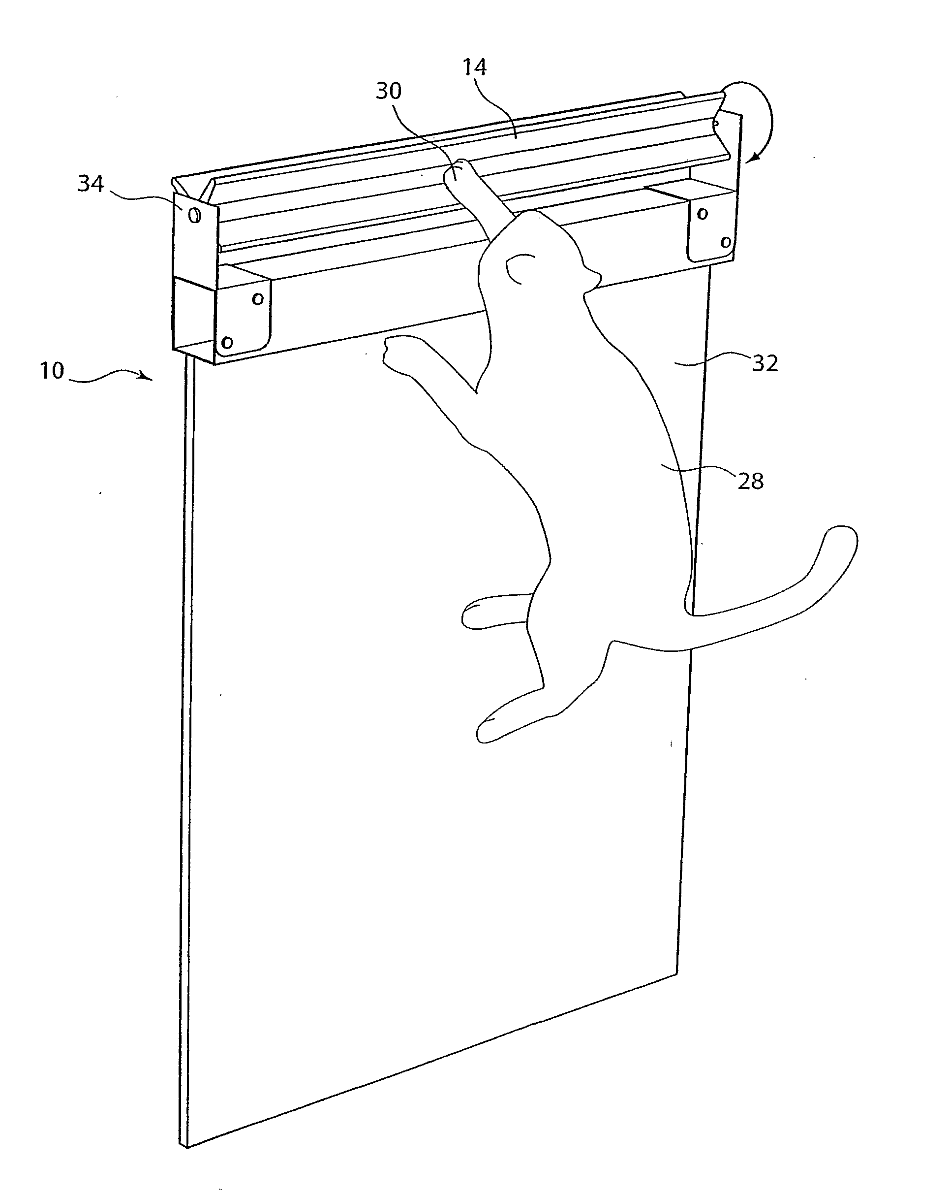
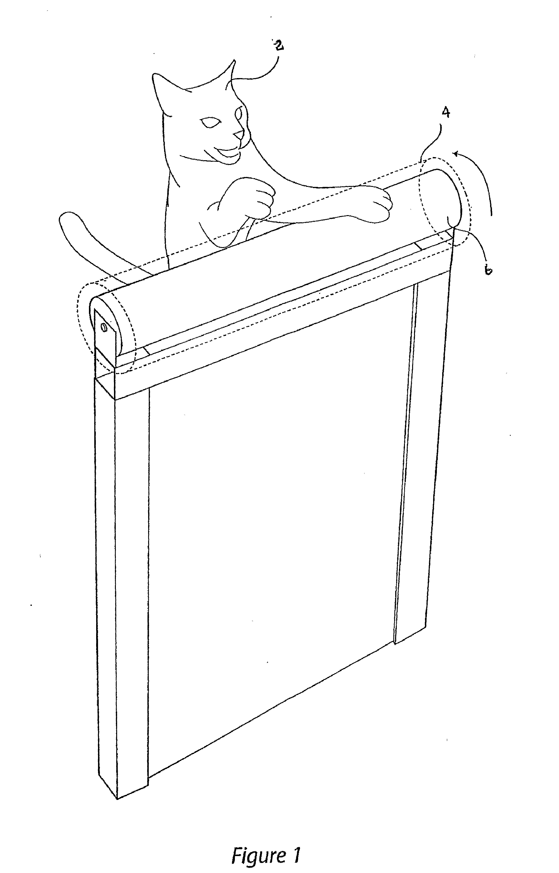
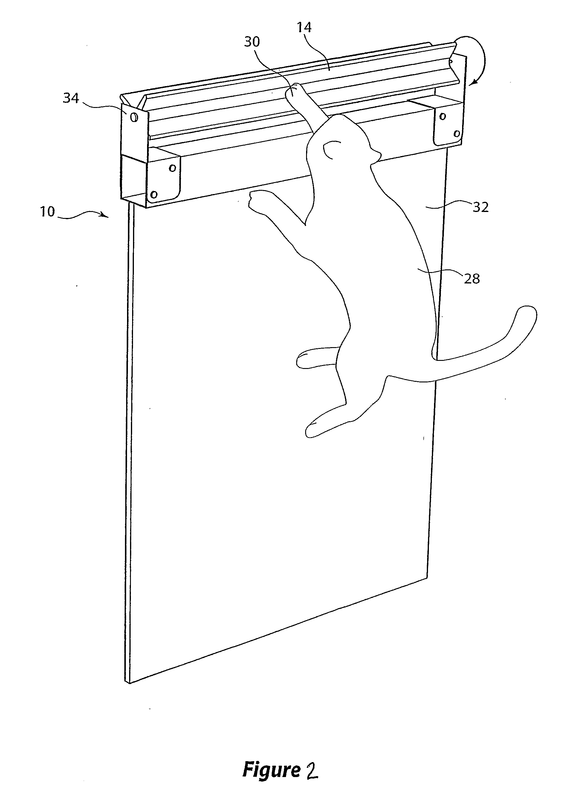
The purpose of this rotatably supported column is that as the cylindrical column will rotate when the domestic pet tries to
gain a foothold or leverage to cross the fence, this unsteadiness of foot caused by the rotation of the column will cause the animal to fall back down.
Advantageously the domesticated animal by not being able to
gain a foothold at the top of the fence means that their ability to scale and jump over the fence is completely hindered.
Currently these kinds of rotating columns or poles presented to the
purchasing public are of a scale that does not effectively hinder the ability of the domestic pet to scale and jump over the fence.
The problem being is that in the attempt to present a rotatable column or pole of dimensions where it can be conveniently fitted to the top of the fence both from a point of view of construction and also aesthetics, is that the consequence is loss of the overall purpose and functionality of the arrangement.
A further problem with such an arrangement is that as the
diameter of the single pole arrangement increases, in order to improve the functionality and the utility of the containment device, so to is the creation of a variety of problematic situations, not the least that one large rotating column could easily capture the paw or leg of the
domestic animal pinning it or
trapping it to the top of the fence.
Still further, if the dimensions of the rotating column or pole are at the level required to prevent the animal from scaling and
jumping over the fence, it is likely then to be of a
structural dimension quite considerable in design, which means its weight and size would make it difficult to simply secure or fasten to a fence and still further the actual aesthetics of the fence is substantially lost, given at the top of the fence is a particularly large pole running along its length.

