Fluid ejection device with reinforced seal

Active Publication Date: 2010-09-16
AIRBUS OPERATIONS SAS
View PDF10 Cites 7 Cited by
  • Summary
  • Abstract
  • Description
  • Claims
  • Application Information

AI Technical Summary

Benefits of technology

[0096]According to a particular embodiment, the elastic ring is formed by a slit ring. This embodiment is particularly economical and reliable, the additional expansion possibilities given by the presence of this slit also facilitating the mounting of the ring. The slit is further used for ensuring the angular position of said ring so that it cannot rotate in its housing and the slit will not be facing an orifice which would cause a loss of the seal.
[0097]Such a fluid ejection device may be easily integrated into a confined environment such as the pod of an aircraft engine, since it is compact and easily integrable, it is not under pressure before and after the emptying phase, and may thus be installed as close as possible to the fire sources without generating any risks, notably risks of explosion, for the surrounding installations, and finally, it only requires very limited maintenance. It may therefore be installed in areas which have limited accessibility without causing excessive maintenance costs.
[0098]Alternatively, such a device may be used as an emergency hydraulic generation device for an aircraft. With such a device hydraulic energy may be provided, required for operating a mechanical control, for example for applications of the braking type and steering on the ground, or even opening and locking the landing gear. For this type of use, the expelled fluid is hydraulic oil. In this case it is preferable not to promote emptying by expelling the gases into the distribution circuit so as to avoid mixing gases and oil. The presence of several reservoirs in parallel allows several maneuvers to be carried out by triggering the latter sequentially.

Problems solved by technology

A significant drawback of this type of pressurized extinguishers is their sensitivity to microleaks, which submits them to severe monitoring, inspection and maintenance conditions.
Indeed, in the absence of thermal insulation, the extinguishing agent may rapidly absorb the calories of the generated gas and thereby reduce the efficiency for ejecting the extinguishing agent.
These volume variations may induce overpressure in the pressurization chamber, which has several major drawbacks.
Indeed, the constraints as regards safety imposed by international regulations in the aeronautical field make the implementation delicate and complex of devices subject to internal overpressure close to areas which may be supplied with extinguishing agent, in particular in proximity to the engines.
Indeed, these devices are likely to be damaged during exterior incidents, for example by ejection of engine parts, by heat or flames.
In the same way, explosion of these devices may damage the relevant areas.
This solution leads to an increase in the overall mass of the extinguisher, which is a penalty for the performances of the aircraft.
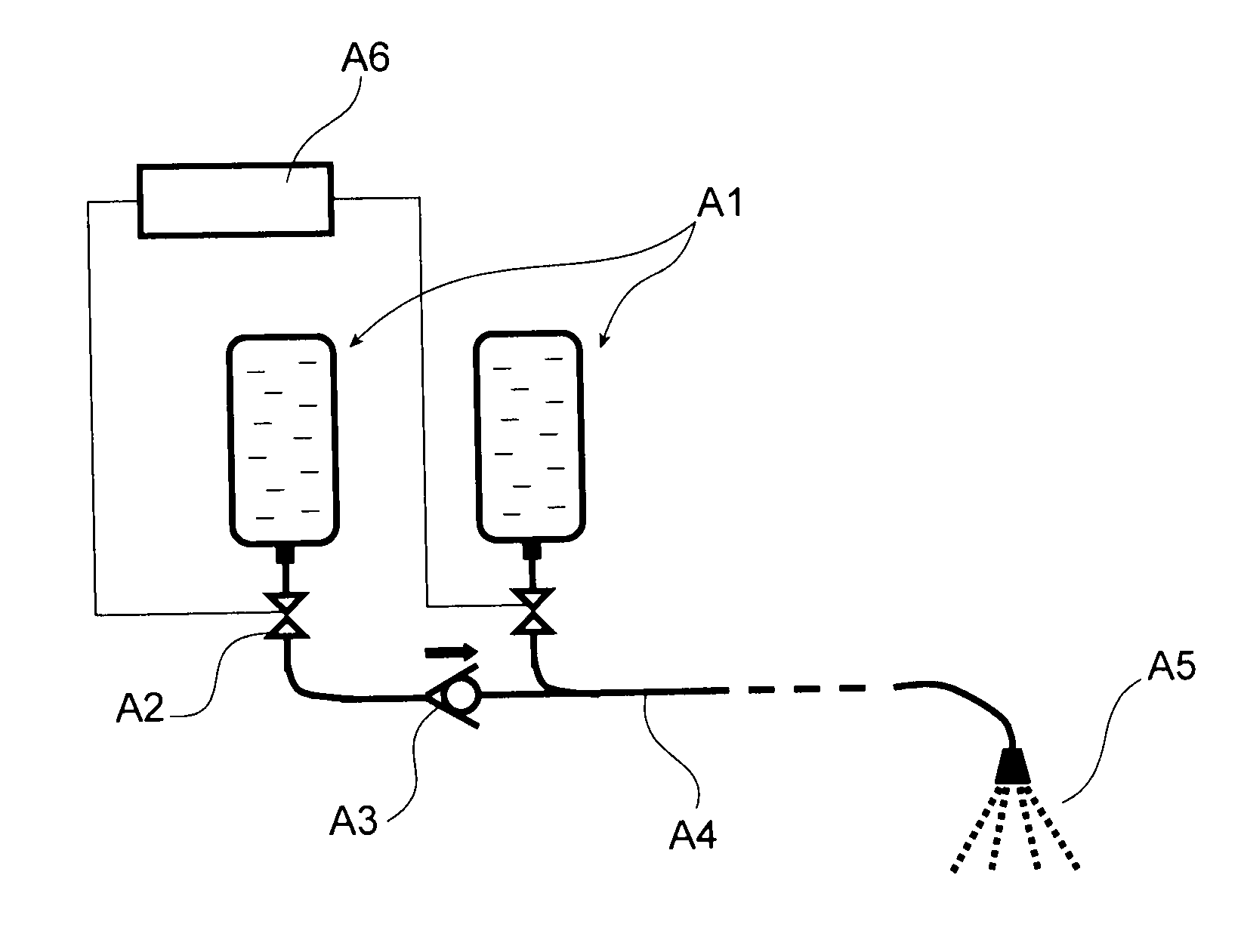
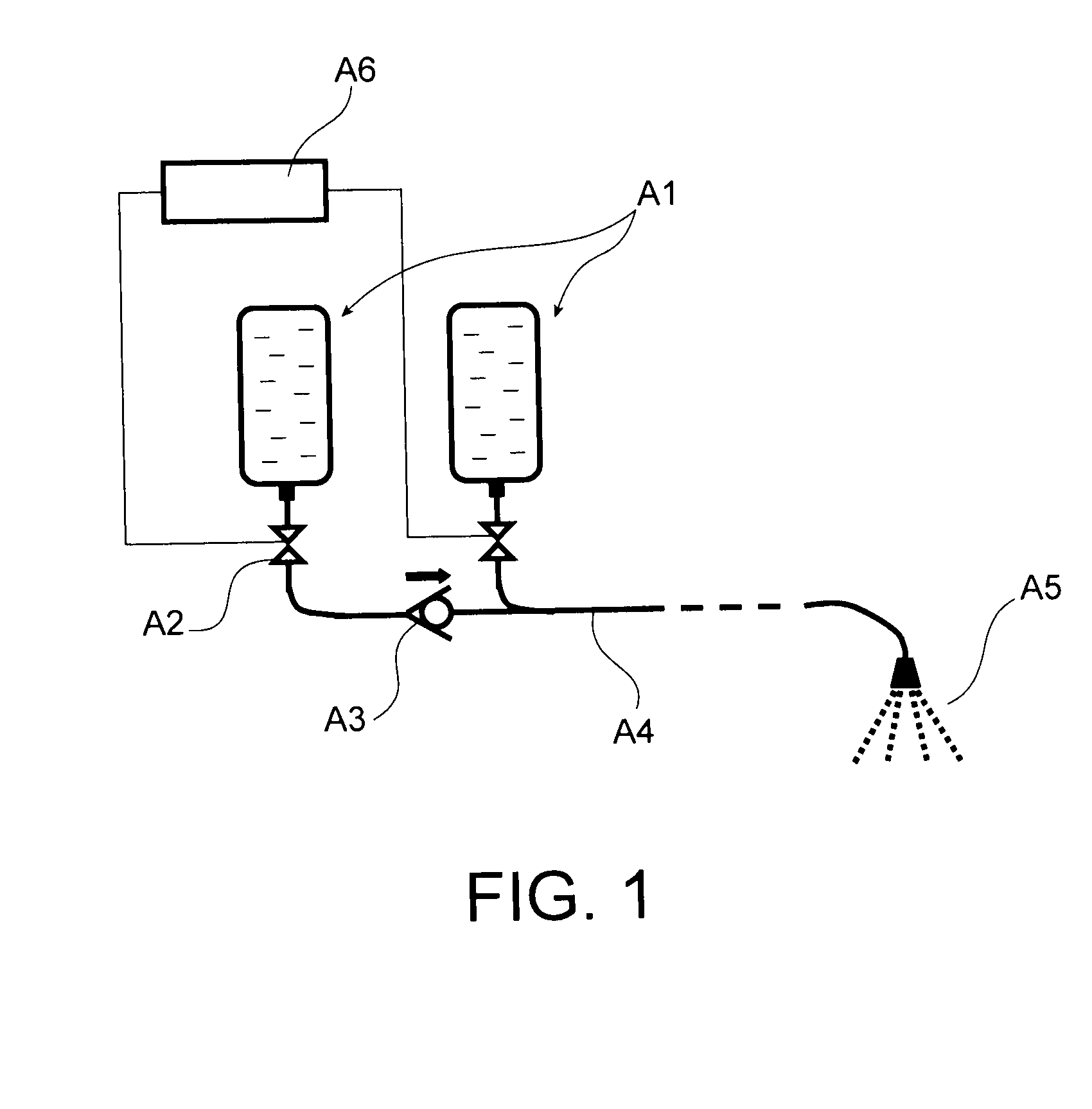
However, moving it away requires the use of a greater distribution duct length between the extinguisher and said areas, which increases the linear pressure loss in the duct and reduces the ejection efficiency.
Further, the required significant duct mass is also a penalty.
This requires a complex control system and valves able to be driven in both directions, opening and closing, i.e. containing mobile parts and subject to sealing defects.
The complexity of such a device makes its maintenance costly and reduces its reliability when it is used for safety devices where said device may remain passive for years and should operate perfectly when the time comes.
On the other hand, once the cap is pierced, the latter can no longer ensure closure of the connection of the reservoir with the distribution circuit.
Indeed, as the distribution circuit A4 is empty when the device is not operating, i.e. during times which may attain years, such valves may be subject to jammings caused by condensation which may occur in such circuits, particularly when the device is installed in an aircraft in a non-pressurized area and is therefore subject to temperature and pressure variations over a large amplitude during each flight.
When it is used as a fire-fighting device or as an emergency device, it may remain inactive for very long periods, which may attain several years and will have to nonetheless operate perfectly when the time comes.
Now, as the piston is caused to slide inside the reservoir, it is difficult to ensure a perfect seal between both chambers while preserving easy slidability of the piston and this for periods which may attain several years.
If the pressurization chamber is sealed against the outside, then accumulation of this fluid in the latter reduces in proportion the efficiency of the pyrotechnic reaction and subsequently that of the ejection of the fluid.
Moreover, particularly if the pressurization chamber is in communication with the outside, condensation phenomena may occur therein.
Water thereby introduced into this chamber may, in the long run, mix with the fluid to be ejected, with the risk of degrading the characteristics of use of the latter.
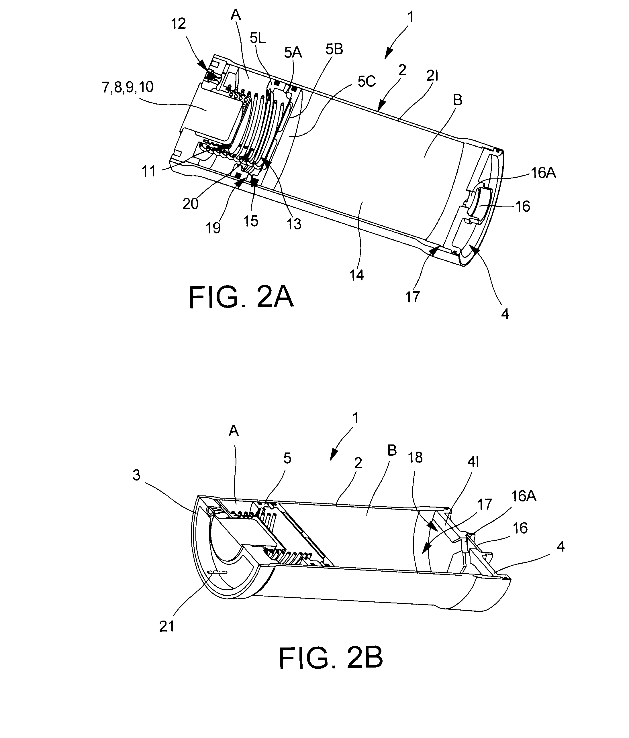
Thus, possible leaks of fluid to be ejected which may occur between the separating element and the wall of the reservoir remain confined between the wall and the thimble.
Thus, in addition to causing translational movement of the piston, the pressure increase in the pressurization chamber causes expansion of the thimble, pressing it against the walls of the reservoir.
With this effect, the operation of the device may be secured even if the sealing means between the piston and the walls of the reservoir have slightly degraded over time and are no longer capable of providing a perfect seal under pressure, therefore particularly at the beginning of the ejection just before and immediately after the opening of the cap.
Indeed, as it is not permanently subject to internal pressure, the device may be built with walls of smaller thickness without degrading its reliability towards risks of bursting.
Checking and, if necessary, correcting this adjustment, entail complex maintenance operations requiring the opening of the fluid ejection devices.
This type of fluid which has very high specific heat would absorb the calories of the pyrotechnic reaction if the gases generated by this reaction would come into contact with it, which would have the consequence of reducing the efficiency of the ejection of the fluid.
Such a fluid ejection device may be easily integrated into a confined environment such as the pod of an aircraft engine, since it is compact and easily integrable, it is not under pressure before and after the emptying phase, and may thus be installed as close as possible to the fire sources without generating any risks, notably risks of explosion, for the surrounding installations, and finally, it only requires very limited maintenance.

Method used


Image

  • Fluid ejection device with reinforced seal
  • Fluid ejection device with reinforced seal
  • Fluid ejection device with reinforced seal

Examples


Embodiment Construction

[0120]FIGS. 2-8 represent a first aspect of the invention.

[0121]As illustrated schematically in FIGS. 2A and 2B, the fluid ejection device comprises as a main element, a reservoir 1 containing the fluid 14 to be ejected, formed by a hollow cylindrical body 2, sealably closed at two ends by a first end portion 3 and a second end portion 4. The cylindrical body 2 may have a circular, elliptical, oblong section, or any other shape of the same kind. The invention more particularly applies to a fluid 14 in the liquid phase. Nevertheless, the fluid 14 may also appear as powders, as pasty fluids or slurries.

[0122]The reservoir 1 includes one or more ejection orifices 16A, which may be connected to distribution means (not shown) in order to allow ejection of the fluid 14 and its conveyance up to a determined area. The ejection orifices 16A are located in the second end portion 4 of the cylinder and in proximity to this end portion. Advantageously, each ejection orifice 16A is sealably close...


PUM


Abstract

A compact device for ejecting a fluid including two chambers separated by a separating element of piston type. One of the chambers contains the fluid intended to be ejected, the other chamber is a pressurization chamber, the pressurization of which can cause translational movement of the separating element and ejection of the fluid. The pressurization chamber includes a thimble capable of sealably separating the inside of the pressurization chamber from the side walls of the reservoir. Thus, a seal between two chambers is perfect and durable without degrading slidability of the piston.

Description

TECHNICAL FIELD[0001]The present invention relates to a fluid ejection device, in particular to an extinguisher or an emergency hydraulic generator used in an aircraft.STATE OF THE PRIOR ART[0002]As regards the use of fluid ejection devices as an extinguisher, it is known that extinguishers with a reservoir of extinguishing agent are classified in two large categories. The first category relates to permanently pressurized apparatuses in which a gas ensures permanent pressurization of the extinguishing agent within a single bottle used as a reservoir for it; the extinguishing agent is released through a valve at the outlet of said bottle. In the second category, a propellant gas is only released upon putting the extinguisher to use and releases the extinguishing agent which is therefore not stored under pressure.[0003]As an illustration of an extinguisher of the first type, extinguishers presently used for putting out an aircraft engine fire may be considered. These devices, not only...

Claims


Application Information

Patent Timeline
IPC IPC(8): B67D7/72A62C35/00
CPCA62C35/023A62C13/66B65D83/643Y10T137/2937A62C3/08
Inventor FABRE, CHRISTIANBIGNOLAIS, ALAIN
Owner AIRBUS OPERATIONS SAS
Why Eureka
Try Eureka