
Radio frequency identification tag with privacy and security capabilities

a technology of privacy and security, which is applied in the field of radio frequency identification tags with privacy and security capabilities, can solve the problems of violating the privacy rights of consumers, unable to use the rfid tag to identify stores, and the privacy of consumers using the rfid tag on consumer goods

Inactive Publication Date: 2010-09-16
MAJKOKH CORP
View PDF11 Cites 78 Cited by
  • Summary
  • Abstract
  • Description
  • Claims
  • Application Information

AI Technical Summary

Benefits of technology

[0013]an RFID integrated circuit secured to said substrate;
[0014]an RFID antenna also secured to said substrate; and wherein said tag is arrangeable in a first configuration in which said integrated circuit and said antenna are operatively electrically coupled to provide an RFID function, and a second configuration in which electric coupling of said antenna and circuit is altered to change said function, with said tag being alterable from said first configuration to said second configuration, and from said second configuration to said first configuration to at least partly reverse said change to said function.

Problems solved by technology

An issue that has arisen regarding the use of RFID tags on consumer goods is the privacy of the consumer.
This may violate the privacy rights of consumers by allowing their shopping habits, movements, or product usage habits to be monitored.
While this would resolve the privacy concerns, it would have the disadvantage that if the consumer item is returned the store will no longer be able to use the RFID tag to identify it.
While this type of solution would resolve the privacy concern, and would allow returned items to be identified by means of the RFID tag, it would have the disadvantage that returned items could not be further processed through a retailer's RFID system due to the limited read distance of the modified tag, and so the returned item would in all probability need to be retagged.
A further disadvantage of using standard RFID tags to identify consumer products is that standard RFID tags do not incorporate any physical security features and so can easily be transferred from one item to another without their RFID function being affected.

Method used


Image

  • Radio frequency identification tag with privacy and security capabilities
  • Radio frequency identification tag with privacy and security capabilities
  • Radio frequency identification tag with privacy and security capabilities

Examples


Embodiment Construction

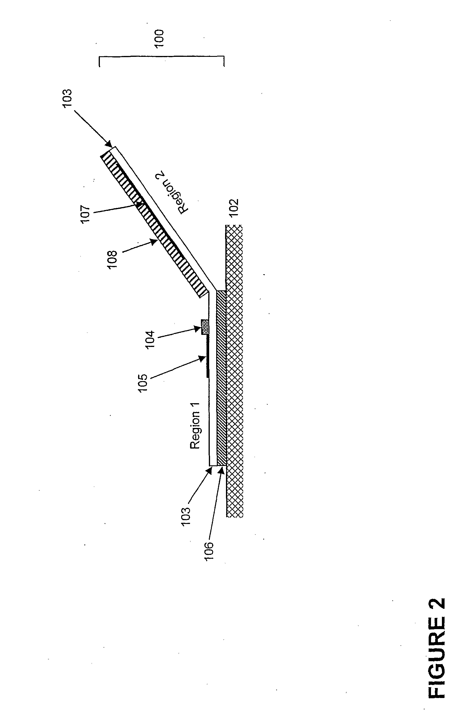
[0032]The present invention will now be described by way of non-limiting example with reference to the embodiments illustrated schematically in FIGS. 1 to 5.

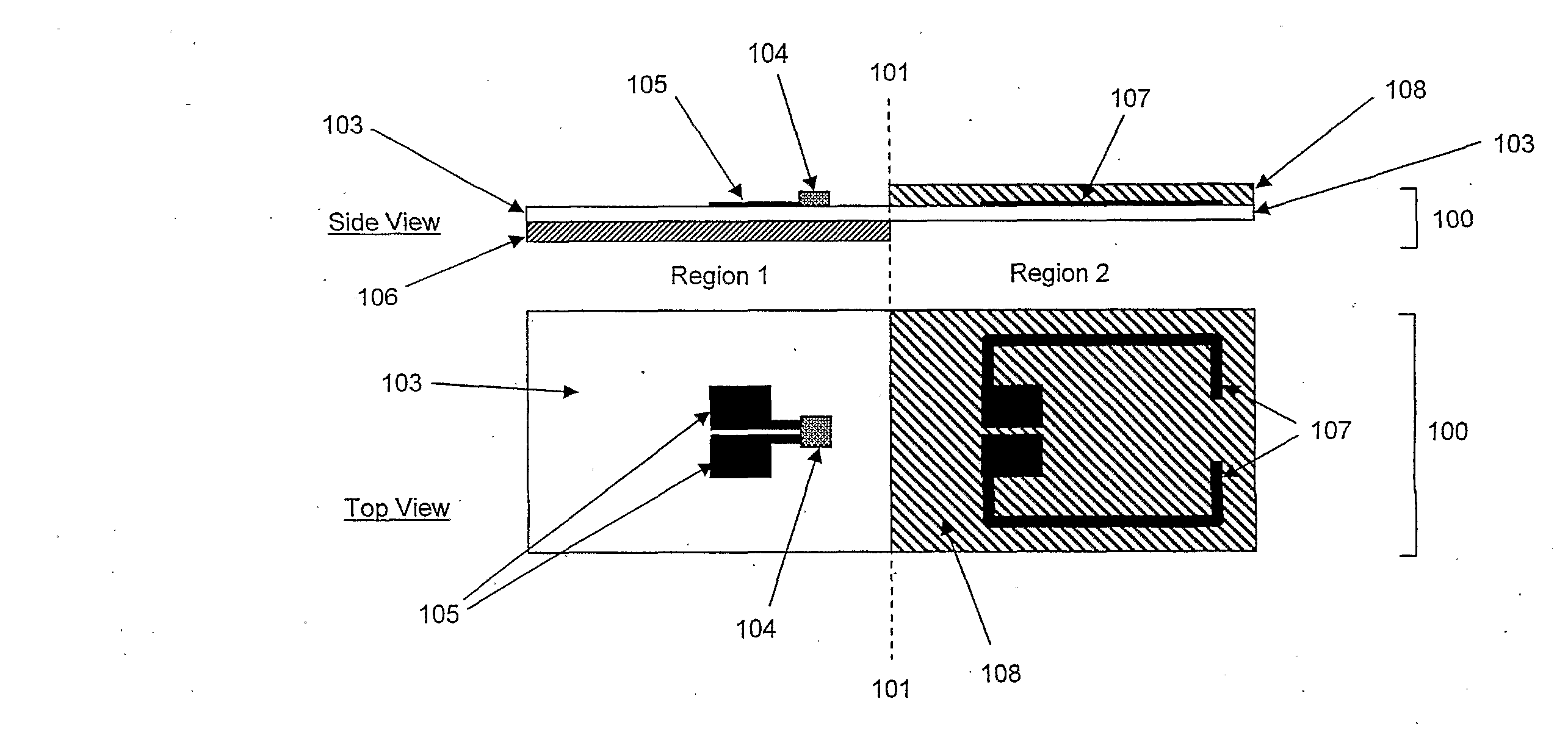
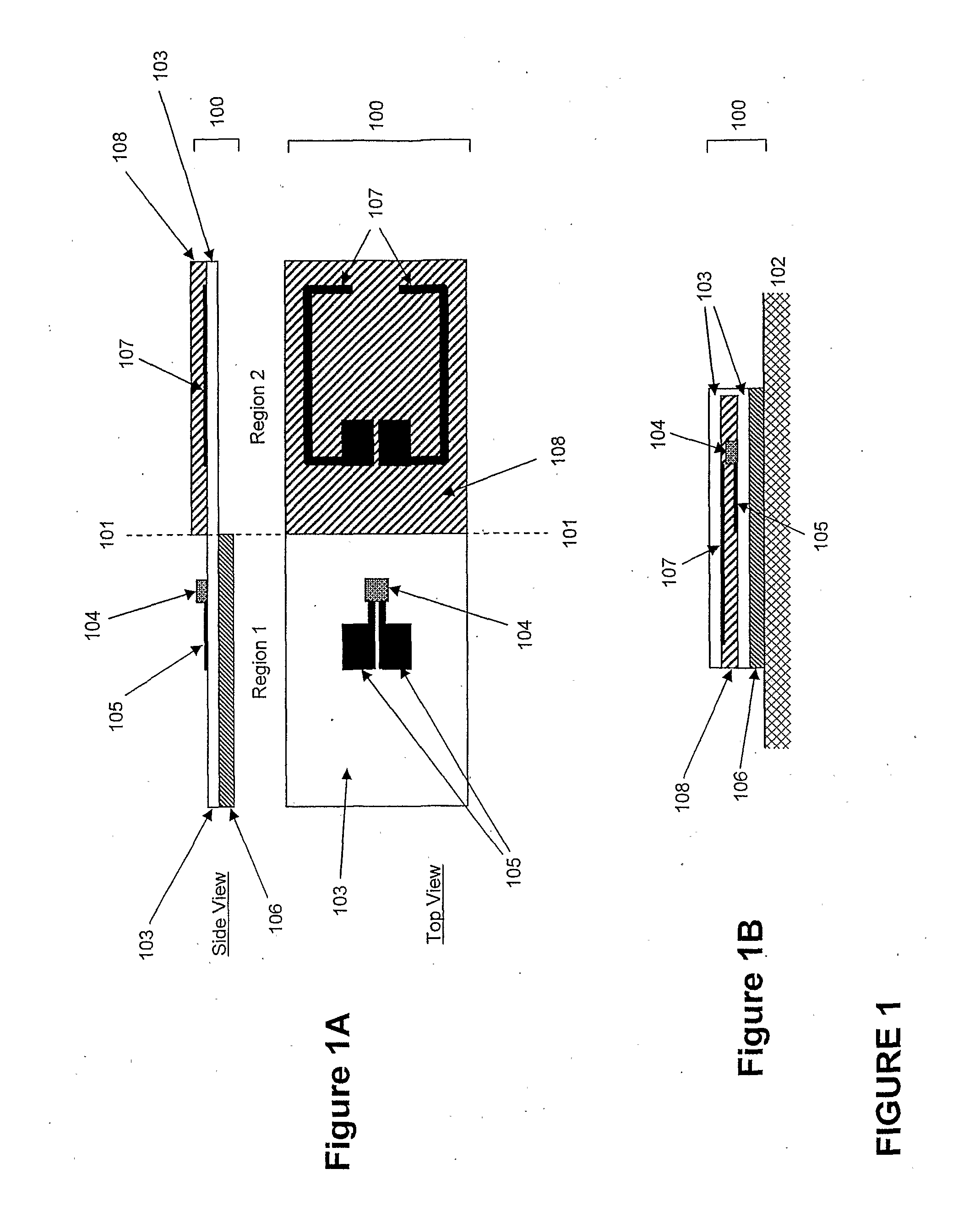
[0033]FIG. 1 is a schematic illustration of an RFID tag that is the subject of the present invention.

[0034]The RFID tag 100 of FIG. 1 is produced initially in the form of a flat rectangular tag having a longitudinal axis, as shown in FIG. 1A. The flat tag of FIG. 1A is folded along a fold line 101 that is transverse of the longitudinal axis into the folded configuration of FIG. 1B that is applied to a surface 102.

[0035]The fold line 101 divides the RFID tag into two regions—region 1 and region 2—as illustrated in FIG. 1A. Regions 1 and 2 do not need to be the same size and shape.

[0036]The preferred embodiment of FIG. 1 is described and illustrated in relation to an RFID tag that incorporates a radio frequency (RF) antenna to enable communication with a remote RFID reading device. It should be appreciated that the antenna design ...


PUM


Abstract

An RFID tag that is foldable about a generally transverse fold line. The line divides the tag into two regions. One region has an RFID integrated circuit and areas of electrically conductive material. The other region has conductive areas that provide an efficient RFID antenna. In a folded configuration the areas are operatively associated with the integrated circuit while in the open configuration the areas are not functionally associated with the integrated circuit. Accordingly in the open configuration the tag is disabled or its RFID performance substantially degraded. The tag can be reversibly altered between the open and folded configurations.

Description

BACKGROUND TO THE INVENTION[0001]Low-cost passive radio frequency identification (RFID) tags are expected to be used in the future to identify and track various items, including consumer products. A typical passive RFID tag includes a thin, flexible substrate to which is applied an RFID integrated circuit (or chip) and radio frequency (RF) antenna. The RF antenna is coupled to the RFID chip and enables communication between the RFID chip and a remote RFID reading device. The tags usually include an attachment means—typically a layer of pressure-sensitive adhesive—to attach the tag to an item. The RFID chip incorporates an electronic memory that typically stores a unique chip identification code and may also have additional storage capability for other data.[0002]RFID technology provides several key advantages over existing automated identification technologies (such as barcode technology), including:[0003]the ability to read an RFID tag from a distance without requiring line-of-sigh...

Claims


Application Information

Patent Timeline
Patent Type & Authority Applications(United States)
IPC IPC(8): G06K19/077
CPCG06K7/10178G06K19/07318G06K19/07345G06K19/0776G06K19/07749G06K19/07756G06K19/07758G06K19/07372
Inventor ATHERTON, PETER SAMUEL
Owner MAJKOKH CORP
Learn More