Self-aligning flanged joint and alignment rim therefor

a flanged joint, self-aligning technology, applied in the direction of fluid pressure sealed joints, cable terminations, mechanical equipment, etc., can solve the problems of not being able to meet one or more stringent requirements for piping and joint systems that might be acceptable for general chemical or industrial processing, and not being able to use materials in aseptic joint systems. , to achieve the effect of reducing maintenance costs and manufacturing downtime, and being convenient to disassembl

Inactive Publication Date: 2010-09-16
FLOWSMART
View PDF8 Cites 20 Cited by
  • Summary
  • Abstract
  • Description
  • Claims
  • Application Information

AI Technical Summary

Benefits of technology

[0020]The use of the substantially rigid outer retaining ring in the gasket assembly limits the axial impingement of the flanges, thereby insuring that a preselected, proper degree of compression of the deformable portion of the gasket assembly is achieved. Excessive tightening, which frequently causes undesirable extrusion and possible removal of deformable gasket material into the bore of the joint assembly, is effectively prevented. Misalignment or misplacement of the gasket assembly within the flange joint is likewise minimized.
[0021]The present flange joint system virtually eliminates the formation of traps in recesses of the joint in which process fluid can collect or stagnate, which frequently leads to the presence or growth of harmful microbes or other pathogenic organisms. The joint is easily assembled and disassembled to permit servicing, including replacement of the gasket assembly. The separability of the sealing member and the retaining ring of the gasket permit the former to be replaced and the latter, which is ordinarily more expensive to manufacture, to be reused. The joint is reliable and durable. The servicing can be carried out expeditiously by personnel who need not have a high level of skill, thereby lessening maintenance costs and manufacturing downtime.

Problems solved by technology

The requirements for joints, including flanged joints, used in process systems that convey food, beverage, pharmaceutical, personal care, or other like products intended for human or animal use through ingestion or external application are especially demanding.
Moreover, no materials can be used in aseptic joint systems that would introduce any harmful or objectionable substances into the process stream for the aforementioned aseptic products.
Many piping and joint systems that might be acceptable for general chemical or industrial processing are not able to satisfy one or more of the stringent requirements associated with processing aseptic products.
For example, some known joint systems have a configuration wherein recesses, crevasses, O-ring grooves, or the like result in dead spaces or stagnation regions in which there is little or no flow of the fluid being transported.
As a result, accumulation of debris likely to give rise to the accumulation and reproduction of pathogens is a serious concern.
Also, some known gasket materials may impart objectionable flavors or even toxic substances into food, beverages, or pharmaceuticals.
Furthermore, the use of certain substances that come into contact with the process fluid may be offensive to adherents of certain religious traditions.
However, in practice a number of problems occur in reliably effecting seals using joints of the type depicted by FIG. 1.
Premature failure of the O-ring to seal commonly results.
Moreover, even if the flanges are accurately aligned and the O-ring seal properly disposed in its grooves, the joint system of FIGS. 1-2 is prone to certain difficulties.
Frequently, such an area becomes a trap, with the deleterious consequences set forth above.
Exposure to required processing temperatures or to corrosive or abrasive process fluids in some cases causes seal materials to erode.
Some materials are embrittled over time by exposure to their process environment.
Moreover, many seal materials exhibit creep or related mechanical phenomena or otherwise lose their elasticity and take a permanent “set.” Joints that are clamped together repeatedly despite poor alignment also are likely to result in wear or damage (e.g. scratching) to mating surfaces 30, 34, which may also compromise seal integrity.
The actual cost of the O-ring and other elastomeric components typically is small in comparison with the labor costs for their replacement and the losses due to manufacturing downtime.
However, the metal parts of the joint are generally far more expensive due to the precision machining and dimensional control needed.

Method used


Image

  • Self-aligning flanged joint and alignment rim therefor
  • Self-aligning flanged joint and alignment rim therefor
  • Self-aligning flanged joint and alignment rim therefor

Examples


Embodiment Construction

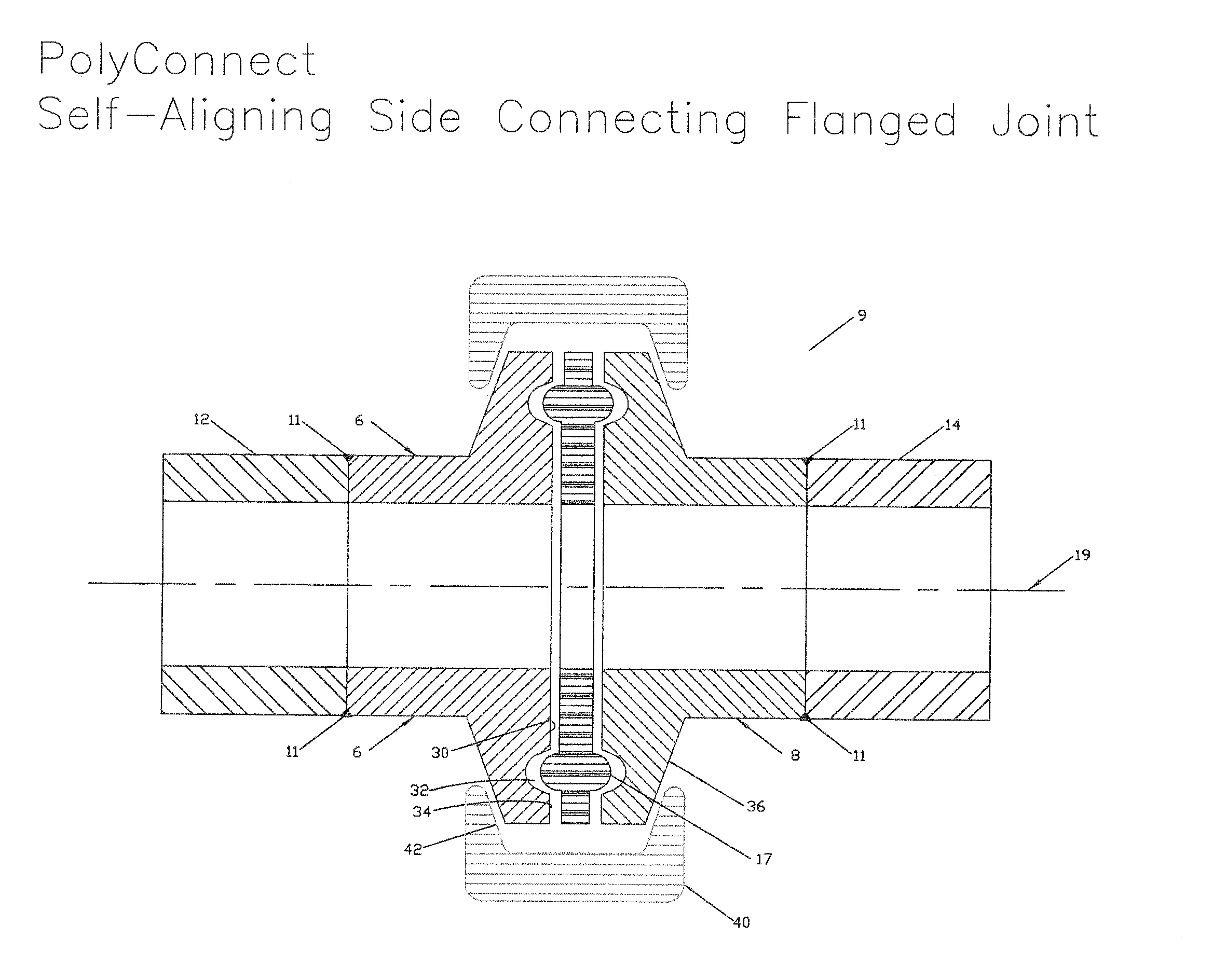
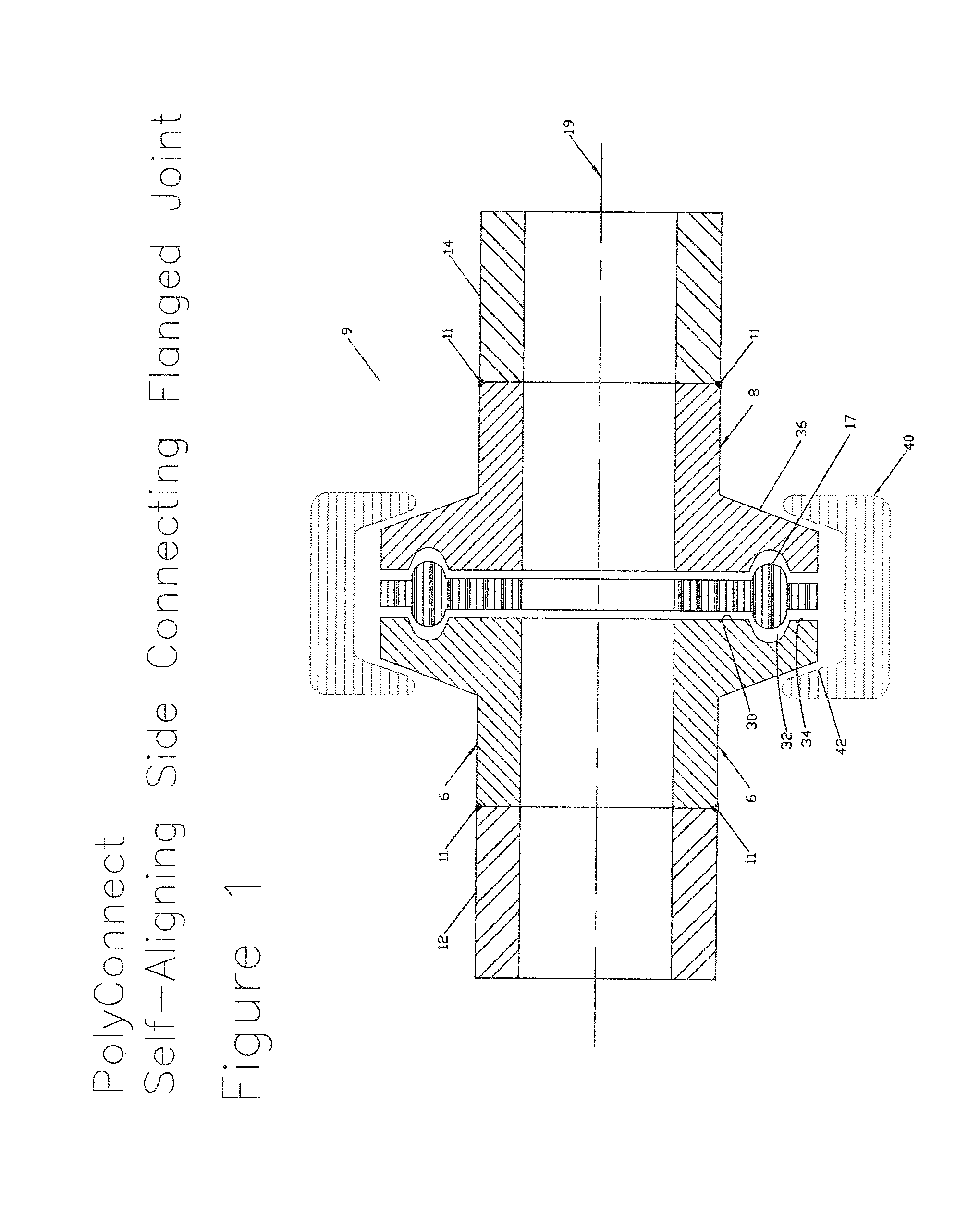
[0041]Referring to FIG. 3A there is depicted an embodiment of a flanged joint system of the invention. Joint 9 connects generally first and second cylindrical tubes 12, 14, which are welded 11 to first and second flanges 16, 18 (also known as ferrules). The terms “tube” and “pipe” are used herein throughout interchangeably and synonymously. Alternatively, the tubes may be attached by any other suitable method, non-exclusively including brazing, soldering, threaded connection, or any other similar technique that provides a durable, leak-resistant connection. Flanges 16 and 18 adjoin in end-to-end relationship about a common center axis 19. The flanges are substantially identical and have mating surfaces generally perpendicular to axis 19. Opposite the mating surfaces are clamping surfaces that include tapered portions 36, which cooperate to form a generally frustoconical outer peripheral surface when the flanges are juxtaposed. The joint is sealed using gasket assembly 20, which comp...


PUM


Abstract

The invention discloses a gasket assembly and a flanged joint system comprising a sealing member, a retaining ring having an outer periphery and an inner periphery wherein said inside periphery being coupled to said sealing member, and an alignment rim that is disposed outwardly from the outer periphery of said retaining ring, but only extends continuously along a portion of said outer periphery, the remainder of the periphery being open to facilitate placement between piping flanges.

Description

CROSS-REFERENCE TO RELATED APPLICATION[0001]This application claims the benefit of U.S. Provisional Application No. 61 / 120,511 filed on Dec. 8, 2008.FIELD OF THE INVENTION[0002]The invention relates to the joining of tubes or pipes, and more particularly, to an aseptic flanged joint. The joint is self-aligning by virtue of a retaining ring that has an alignment rim extending outwardly and continuously around a portion only of the outer circumference of the ring. That portion of the ring not comprising the alignment rim is thus easily disposed between the joint, by e.g. slipping it between same, without necessitating the dismantling of all or part of the assembly or the undue prying apart of the terminal flanges; whereas that portion of the ring comprising the rim secures and aligns the joint. In select embodiments, the alignment rim extends over about one half of the retaining ring outer circumference while the other half of the retaining ring remains open, i.e. lacks the rim.DESCRI...

Claims


Application Information

Patent Timeline
Patent Type & Authority Applications(United States)
IPC IPC(8): F16L23/00F16L17/00F16J15/06
CPCF16J15/061F16L23/24F16L23/10
Inventor BONGIORNO, LOUIS CHARLES
Owner FLOWSMART
Why Eureka
Try Eureka