
Server controller and a method for controlling a plurality of motors

a server controller and motor technology, applied in the direction of electric controllers, program control, instruments, etc., can solve the problems of inability to move the motors to exactly the same position, inability to handle vibration in the sub-motor, and inability to distribute the torque between the motors equally, so as to reduce the drawbacks

Inactive Publication Date: 2010-09-16
ABB TECH AG
View PDF3 Cites 27 Cited by
  • Summary
  • Abstract
  • Description
  • Claims
  • Application Information

AI Technical Summary

Benefits of technology

"The present invention provides an improved server controller for controlling a plurality of motors that reduces the drawbacks of existing methods. The server controller uses a master motor to control a movable member and a slave motor that work together to move the member. The master motor controls the speed of the master motor and the slave motor controls the speed of the slave motor. The server controller calculates reference torque for the master motor and the slave motor based on position errors for each motor. The server controller is designed to distribute torque between the motors so that they work equally and independently. The method also includes a mutual integral torque component that takes into account the relation between the maximum torque of the motors and the total maximum torches. This allows for a more accurate distribution of torque between the motors. The server controller and method can be easily implemented and do not require any extra damping equipment."

Problems solved by technology

The method aims that both motor shafts will reach the same position, possibly with the same control error.
A problem with this type of server control is that it cannot handle vibrations in the sub-motor if the master motor is not vibrating.
However, if the mechanical coupling between the two motors is stiff, the torque between the motors will not be distributed equally if there is a mechanical offset or backlash between the motors.
In reality it is not possible to move the motors to exactly the same position, due to mechanical imperfections, backlash in gears, differences between the position detectors, or bad calibration of the detectors, which means that the motors are not in the correct position from the beginning.
The consequence is that the two control sections try to get both motors exactly to the reference position, which is impossible, and the movable member becomes inclined instead of straight.
Then large amounts of heat will be generated and there is a risk for the motors to become overheated

Method used


Image

  • Server controller and a method for controlling a plurality of motors
  • Server controller and a method for controlling a plurality of motors
  • Server controller and a method for controlling a plurality of motors

Examples


first embodiment

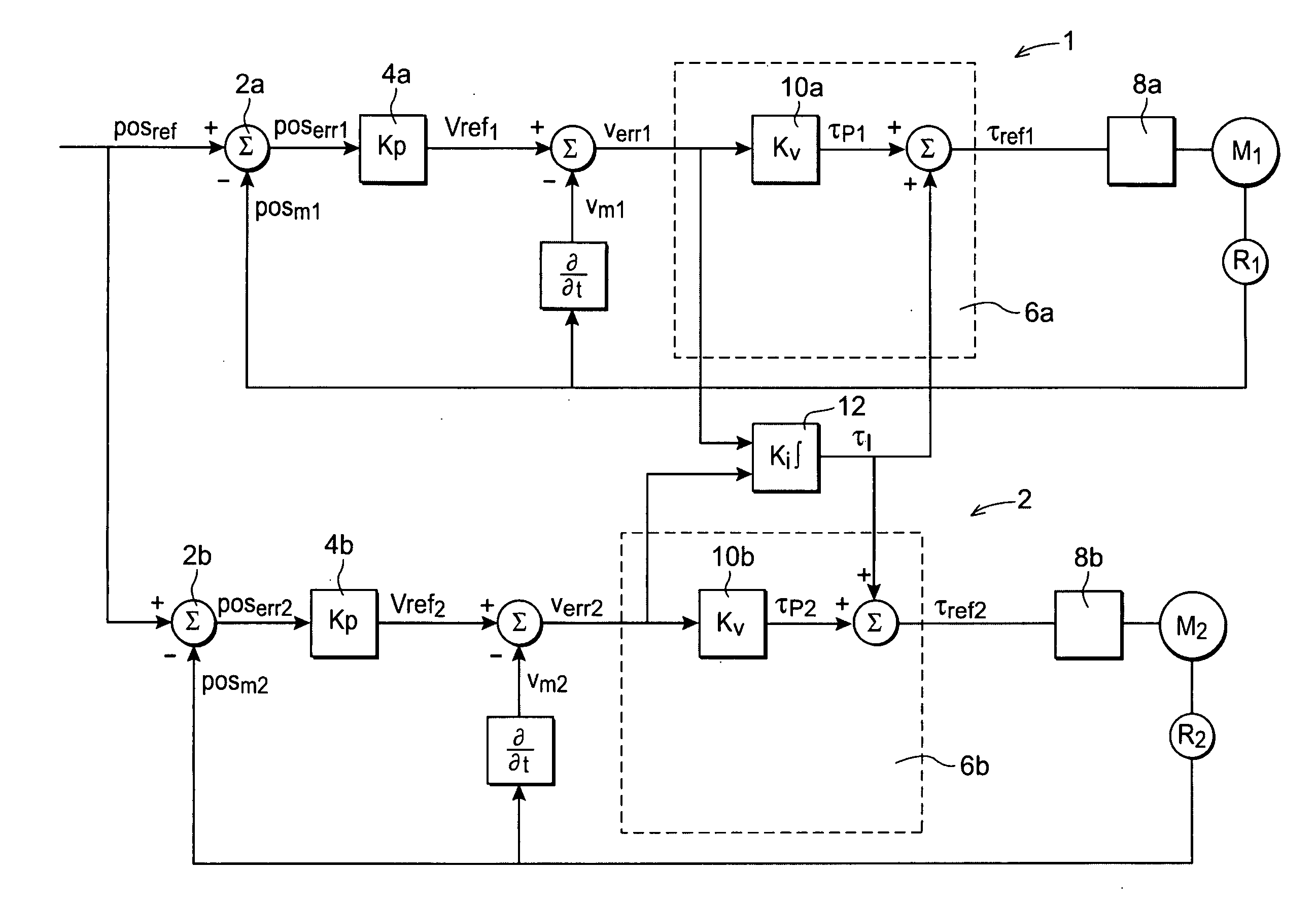
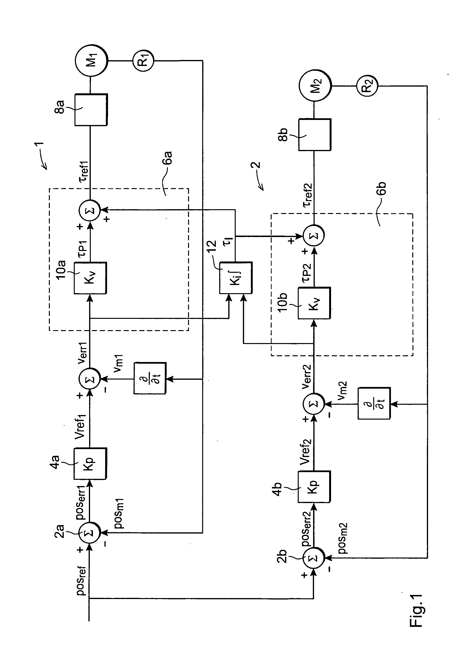
[0026]FIG. 1 shows a server controller for controlling two motors M1, M2 according to the invention. The motors M1 and M2 are configured to cooperatively drive a movable member (not shown). The server controller comprises a first control section 1 configured to control the master motor M1 and a second control section 2 configured to control the slave motor M2. The server controller is provided with position references posref from a main computer. The same position reference posref is used for both motors. In this example, the motor M1 is a master motor and the motor M2 is a slave motor. The position reference is, for example, joint angles for a shaft driven by the motor.

[0027]Each control section 1,2 is provided with a position detector R1, R2 detecting the position of the shaft driven by the motor. The first control section 1 is provided with measured positions posm1 from the master motor and the second control section 2 is provided with measured positions posm2 from the slave moto...

second embodiment

[0051]FIG. 3 shows the second embodiment implemented for a plurality of motors, in this case three motors M1-3, cooperatively driving a movable member. One of the motors M1 is master motor and the other motors are slave motors. If there is more than one slave motor, the updates of the integral values are only done from the slave speed controllers to the master speed controller. The second slave speed controller uses the master integral value updated by the first slave speed controller. The server controller includes three control sections, each control section including a speed controller 30a-c. The first speed controller 30a is configured to provide the current controller 8a of the master motor M1 with torque references τref1 and the second speed controller 30b and the third speed controller 30c are configured to provide the current controllers 8b-c of the two slave motors M2, M3 with torque references τref2, τref3. Each of the speed controllers 30a-c is provided with a proportiona...

third embodiment

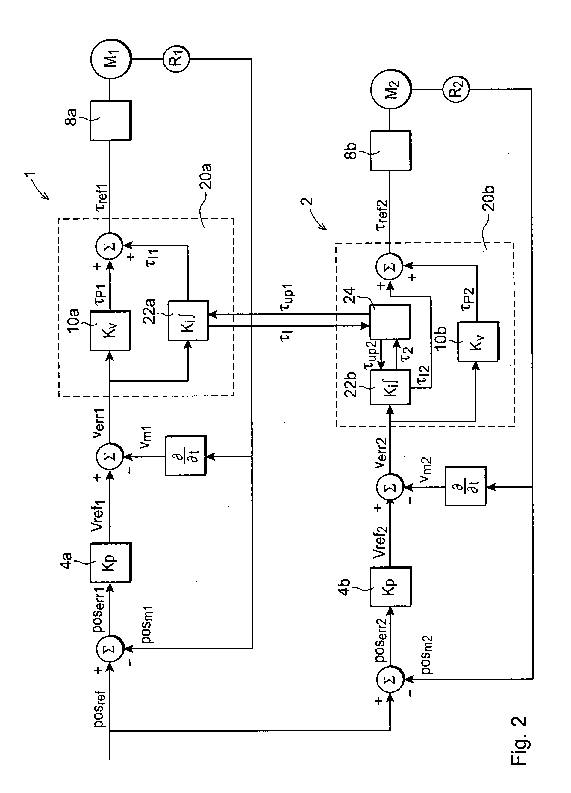
[0057]FIG. 4 shows a server controller for controlling at least two motors M1-2 according to the present invention. The speed controllers 20a-b are configured in the same way as described with reference to FIG. 2. In this embodiment the input to position controllers 38a, 38b is a common position error poserr for the master motor and the slave motor. The common position error is calculated by a position error computer 36 based on the position error poserr1 for the master motor and the position error poserr2 for the slave motor. For example, the position error is calculated according to the following formula:

poserr=poserr1*X+poserr2*(1−X) 01

[0058]Accordingly, if X=0 the common position error poserr is the position error for the slave and if X=1, the common position error is equal to the position error for the master. If X is any value between 0 and 1, the position error for the master and slave is weighted between the master and slave motor. According to this embodiment, the position ...


PUM


Abstract

Servo controller for controlling a plurality of motors including a master motor and a slave motor cooperatively driving a movable member. The servo controller is configured to control the master motor and the slave motor based on position references for the master motor. The servo controller includes a master speed controller configured to calculate a reference torque for the master motor based on speed errors for the master motor. The slave speed controller is configured to calculate reference torques for the slave motor based on speed errors for the slave motor. Each of the reference torques includes a proportional torque part and an integral torque part. The servo controller is configured to calculate each of the integral torque parts based on the speed errors of the master motor and the speed errors of the slave motor, such that the torques due to the integral torque parts will be distributed equally between the master and slave motors or according to a predefined ratio.

Description

FIELD OF THE INVENTION[0001]The present invention relates to a server controller for controlling a plurality of motors including a master motor and a slave motor cooperatively driving a movable member.[0002]The present invention also relates to a method for server control of at least two motors cooperatively driving a movable member.PRIOR ART[0003]In drive mechanisms for robots, machine tools, injection molding machines, pressing machines, positioners, etc., it is often the case that a movable member to be actuated is too large in size to be accelerated or decelerated by a single motor for driving the movable member. In such cases, two or more motors are used for cooperatively driving the movable member. When performing the control of the motors, drive shafts of the individual motors need to be subjected to position control.[0004]It is well known to use servo controllers for controlling the position of a motor. For example, a servo controller for controlling a motor driving the moti...

Claims


Application Information

Patent Timeline
Patent Type & Authority Applications(United States)
IPC IPC(8): G05B11/42G05B11/32
CPCG05B19/258G05B19/318G05B19/378H05K7/1452G05B2219/42186H02P5/46G05B2219/42033
Inventor JONSSON, INGVAR
Owner ABB TECH AG
Learn More