
Induction regulator for power flow control in an ac transmission network and a method of controlling such network

a technology of power flow control and transmission network, which is applied in the direction of electric variable regulation, process and machine control, instruments, etc., can solve the problems of not being able to force current, reactance can only be reduced to a certain level, and generators be planned in a non-optimal way, so as to achieve the effect of controlling permeability

Inactive Publication Date: 2010-09-16
ABB RES LTD
View PDF23 Cites 1 Cited by
  • Summary
  • Abstract
  • Description
  • Claims
  • Application Information

AI Technical Summary

Problems solved by technology

If unforeseen events occur in a network, it will require that the generators be planned in a non-optimal way with regard to the production costs.
When influencing the active power flow by using a series capacitor, the reactance can only be reduced to a certain level and it is not possible to force the current irrespective of the state of the line since it is not possible in practice to overcompensate the line.
The disadvantages of existing UPFCs have primarily been associated with the difficulty of protecting the power electronics on the series-transformer side.
The control speed is low and considerable mechanical force is required to achieve the slow change of the output voltage.
An disadvantage of the induction regulator is that the voltage amplitude is changed when the angle δ is changed.
A device according to the first category is able to control the power flow within minimum and maximum ranges almost independently of the load states, whereas a control device according to the second category cannot always fulfil this requirement.
A drawback of the induction regulator is that the possibilities of control are limited to the voltage change that the secondary voltage vector achieves and this while changing the phase angle of the voltage.
This renders parallel connection of lines and apparatus difficult, since an angular rotation brings about a voltage change and hence a circulating reactive effect.

Method used


Image

  • Induction regulator for power flow control in an ac transmission network and a method of controlling such network
  • Induction regulator for power flow control in an ac transmission network and a method of controlling such network
  • Induction regulator for power flow control in an ac transmission network and a method of controlling such network

Examples


Embodiment Construction

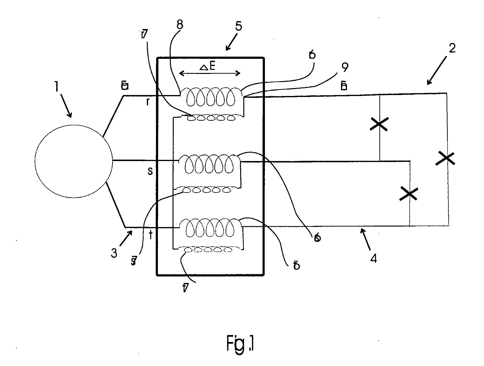
[0046]In the description and the figures below, the invention is only exemplified for control of a three-phase network with the phases r, s, t, since three-phase distribution networks are the most commonly used in practice, whereas the invention as such is applicable also to a polyphase network with a different number of phases.

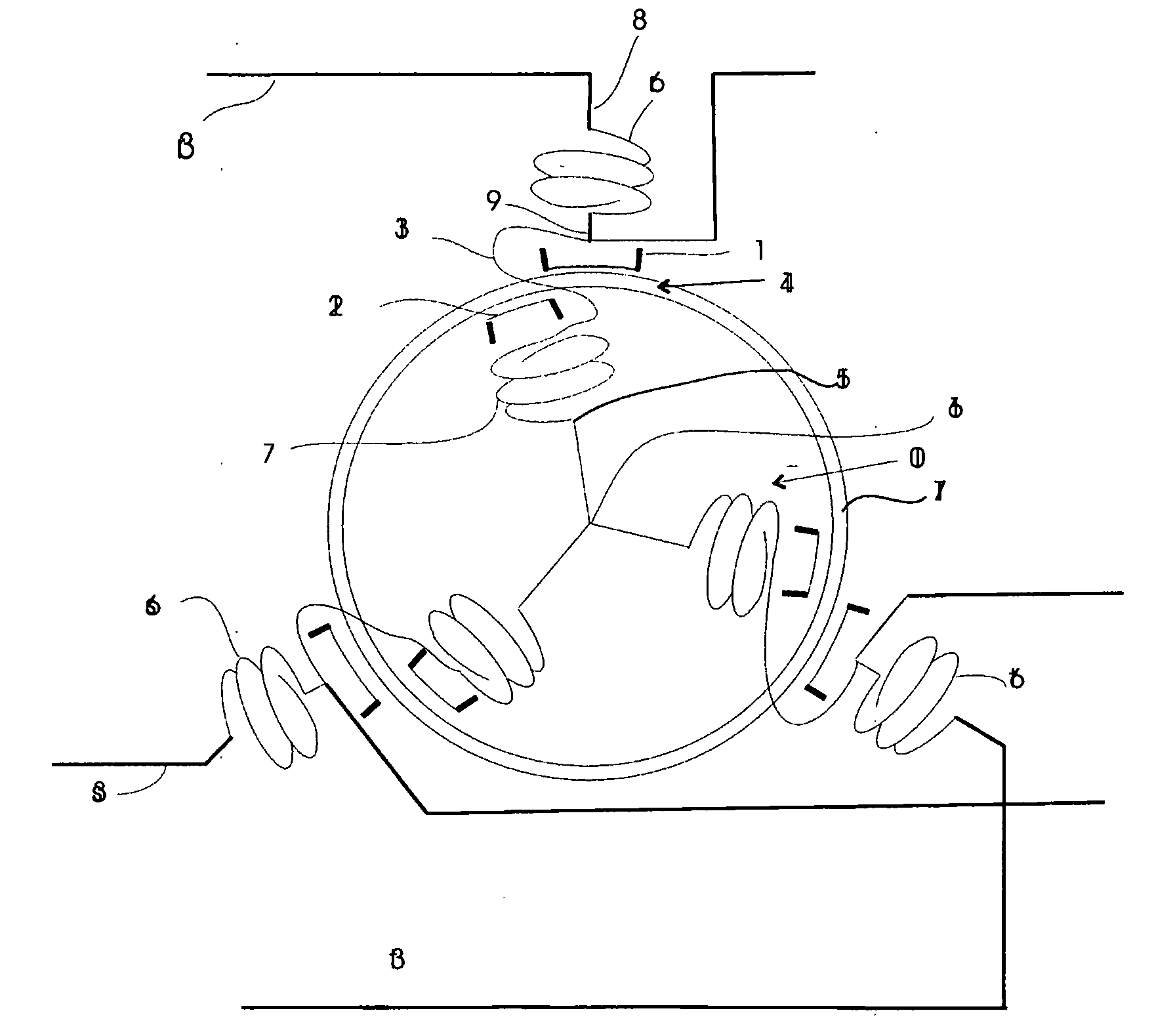
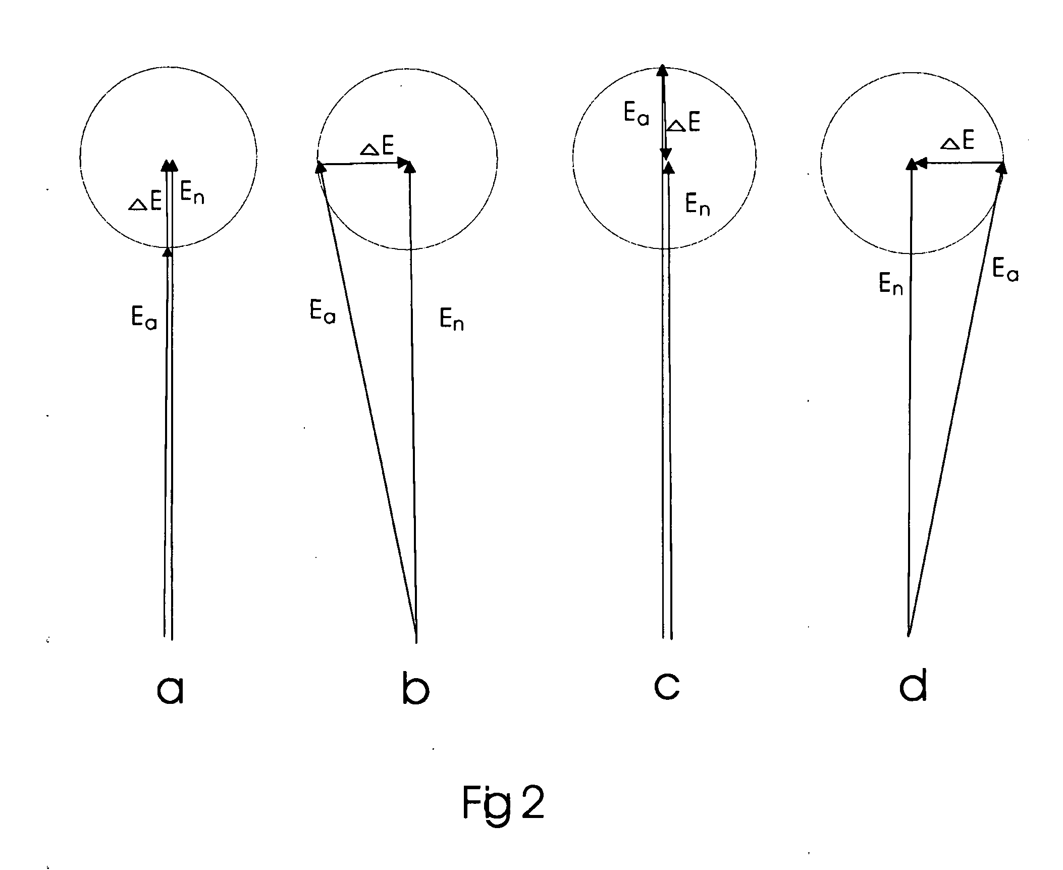
[0047]In FIG. 1, 1 denotes a source of current that is connected to a consumer 2 via a three-phase network with its three phases 3r, 3s and 3t, said network exhibiting a primary side 3 and a secondary side 4. An induction regulator 5 is connected between the current source and the consumer. Between the current source 1 and the induction regulator 5, the phase voltage Ea in the network is variable, whereas the phase voltage En in the network between the induction regulator and the consumer is maintained constant. The induction regulator exhibits three stator windings 6r, 6s and 6t and three rotor windings 7r, 7s and 7t. The respective stator winding exhibits a...


PUM


Abstract

A device for controlling the voltage and the phase angle of a polyphase electric transmission network including an induction regulator that is connected between the primary side and the secondary side of the transmission network. A gap is provided with a magnetic layer having a relative permeability that is controllable, wherein the magnitude (amplitude) of the secondary voltage vector is also adapted to be controlled by controlling the permeability of the magnetic layer. The magnetic layer may include a magnetic fluid or a solid material.

Description

FIELD OF THE INVENTION[0001]The present invention relates to an induction regulator for controlling the voltage and the phase angle of a polyphase electric transmission network, which induction regulator is connected between a primary side and a secondary side of the transmission network and comprises a stator with stator windings and stator poles and a partial rotatable rotor with rotor windings and rotor poles, and a gap between the respective stator pole and rotor pole.[0002]The invention also relates to a method of controlling voltage and phase angle of a polyphase transmission network.[0003]The invention further relates to use of a power-flow control device for a polyphase transmission network for high voltage.DESCRIPTION OF THE BACKGROUND ART[0004]The active power flow in an ac network is controlled by the equationP=U1U2Xsinδwhere U1 and U2 are the voltages at the transmitting and receiving ends, respectively, of the network. The line reactance is X and δ is the angle between ...

Claims


Application Information

Patent Timeline
Patent Type & Authority Applications(United States)
IPC IPC(8): H02J3/18
CPCH01F3/10H01F29/00Y02E40/32H02J3/1885H01F2003/106Y02E40/30
Inventor DAHLGREN, MIKAELJOHANSSON, STEFAN
Owner ABB RES LTD
Learn More