High efficiency buck-boost power converter

Inactive Publication Date: 2010-09-16
RICHTEK TECH +1
View PDF6 Cites 49 Cited by
  • Summary
  • Abstract
  • Description
  • Claims
  • Application Information

AI Technical Summary

Benefits of technology

[0005]An object of the present invention is to provide a buck-boost power converter and a control method thereof, which use a novel switching sequence to lower switching loss and conduction loss when an input voltage approaches an output voltage.
[0006]Another object of the present invention is to provide a buck-boost power converter and a control method thereof, which extend switching periods of switches to lower switching loss when an input voltage approaches an output voltage.
[0007]Yet another object of the present invention to provide a buck-boost power converter and a control method thereof, which take into account the influence of a load current on a buck-boost duty so as to switch modes at the correct time points and thereby not to affect the output voltage by the mode switching.
[0

Problems solved by technology

However, the waveforms of the sawtooth signals SAW1 and SAW2 are not ideally linear near the peaks and the valleys, and therefore, when the input voltage Vin approaches the output voltage Vout, i.e., when the signal PWM1 or PWM2 ha

Method used


Image

  • High efficiency buck-boost power converter
  • High efficiency buck-boost power converter
  • High efficiency buck-boost power converter

Examples


first embodiment

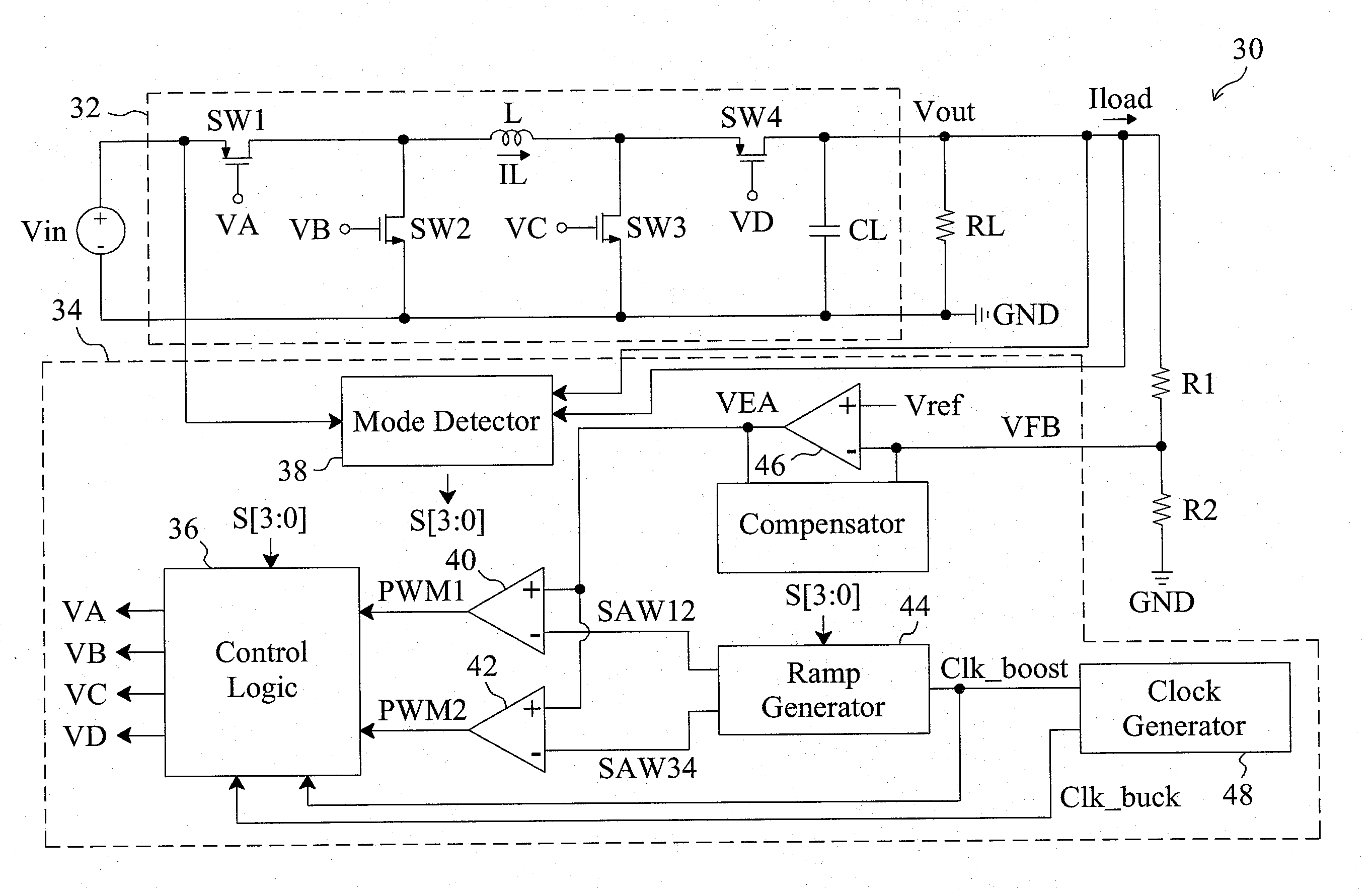
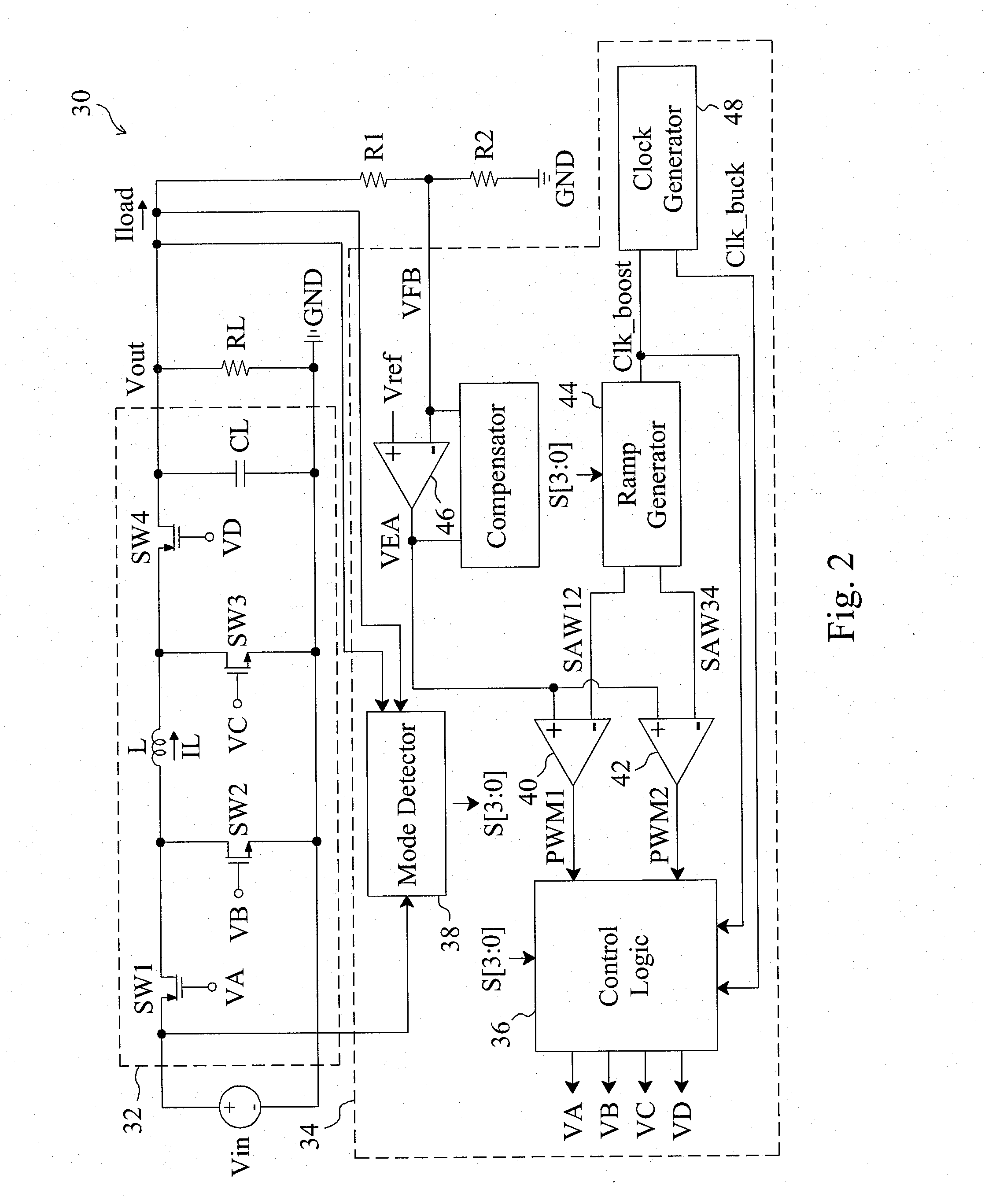
[0026]A first embodiment according to the present invention is shown in FIG. 2, in which a buck-boost power converter 30 includes a control circuit 34 to provide control signals VA, VB, VC and VD to drive a power stage 32, so as to convert an input voltage Vin into an output voltage Vout that is divided by voltage divider resistors R1 and R2 to generate a feedback signal VFB for the control circuit 34. In the power stage 32, a switch SW1 is coupled between the power input terminal Vin and an inductor L, switches SW2 and SW3 are coupled between two terminals of the inductor L and a ground terminal GND respectively, and a switch SW4 is coupled between the inductor L and the power output terminal Vout. The duty of the entire system is not only related to the input voltage Vin and the output voltage Vout, but also affected by a load current Iload. Therefore, according to the present invention, the load current Iload is also taken into account when determining the time points at which th...

second embodiment

[0035]By replacing the switch SW4 in the buck-boost power converter 30 of FIG. 2 with a diode D1, a second embodiment according to the present invention is provided as shown in FIG. 13. The control and operation of this buck-boost power converter 130 is similar to that of the buck-boost power converter 30 of FIG. 2. When the buck-boost power converter 130 operates in the buck-boost modes, the switches SW1-SW3 are switched in the sequence that (1) the switch SW2 is turned on and the switches SW1, SW3 are turned off, (2) the switch SW1 is turned on and the switches SW2, SW3 are turned off, and (3) the switches SW1, SW3 are turned on, and the switch SW2 is turned off. These steps 1-3 are repeated in the same sequence. When the voltage ratio between the two terminals of the inductor L, determined by the input voltage Vin, the output voltage Vout, and the load current Iload, is greater than a first threshold value but smaller than one, the switch SW3 has a fixed duty. When the voltage ra...

third embodiment

[0036]By replacing the switch SW2 in the buck-boost power converter 30 of FIG. 2 with a diode D2, a third embodiment according to the present invention is provided as shown in FIG. 14. The control and operation of this buck-boost power converter 140 is similar to that of the buck-boost power converter 30 of FIG. 2. When the power converter 140 operates in the buck-boost modes, the switches SW1, SW3, SW4 are switched in the sequence that (1) the switch SW4 is turned on and the switches SW1, SW3 are turned off, (2) the switches SW1, SW4 are turned on and the switch SW3 is turned off, and (3) the switches SW1 and SW3 are turned on and the switch SW4 is turned off. These steps 1-3 are repeated in the same sequence. When the voltage ratio between the two terminals of the inductor L, determined by the input voltage Vin, the output voltage Vout, and the load current Iload, is greater than a first threshold value but smaller than one, each of the switches SW3 and SW4 has a fixed duty. When ...


PUM


Abstract

A buck-boost power converter switches the switches thereof with a novel sequence and extends the switching periods of the switches to reduce the switching loss and conduction loss when the input voltage thereof approaches the output voltage thereof. The influence of the load current of the power converter on the duty thereof is taken into account to switch the power converter between modes at correct time points, so as to prevent the output voltage from being affected by the mode switching.

Description

FIELD OF THE INVENTION[0001]The present invention is related generally to a buck-boost power converter and, more particularly, to a control circuit and method for switching loss reduction and smooth mode transition of a buck-boost power converter.BACKGROUND OF THE INVENTION[0002]As shown in FIG. 1, a conventional buck-boost power converter 10 includes a power stage 12 operated by a control circuit 14. In the power stage 12, a switch SW1 is coupled between a power input terminal Vin and an inductor L, switches SW2 and SW3 are coupled between two terminals of the inductor L and a ground terminal GND respectively, and a switch SW4 is coupled between the inductor L and a power output terminal Vout. Voltage divider resistors R1 and R2 divide the output voltage Vout to generate a feedback signal VFB. In the control circuit 14, an error amplifier 24 generates an error signal VEA according to the feedback signal VFB and a reference voltage Vref, a ramp generator 22 provides two sawtooth sig...

Claims


Application Information

Patent Timeline
IPC IPC(8): G05F1/10
CPCH02M3/1582
Inventor CHEN, KE-HORNGWU, WEI-QUANHO, HSIN-HSIN
Owner RICHTEK TECH
Why Eureka
Try Eureka