Stereoscopic Binocular System, Device and Method

a binocular system and binocular lens technology, applied in the field of optics, can solve the problems of not being able to easily miniaturize, heavy crt display, heavy, etc., and achieve the effect of improving the quality of the imag

Inactive Publication Date: 2010-09-16
MIRAGE INNOVATIONS
View PDF6 Cites 84 Cited by
  • Summary
  • Abstract
  • Description
  • Claims
  • Application Information

AI Technical Summary

Benefits of technology

[0048]The present invention successfully addresses the shortcomings of the presently known configurations by provid...

Problems solved by technology

Unless a person is long-sighted, he may not be able to view a sharp image at a closer distance.
The CRT displays are heavy, bulky and not easily miniaturized.
The active matrix panel uses a transistor to control each pixel, and is more expensive.
Small size real image stereoscopic displays are hardly attainable because they have a relatively small surface area on which to present a real image, thus have limited capability for providing sufficient information to the user.
For example, such displays have suffered from being too heavy for comfortable use, as well as too large so as to be obtrusive, distracting and even disorienting.
These defects stem from, inter alia, the incorporation of relatively large optics systems within the mounting structures, as well as physical designs which fail to adequately take into account important factors as size, shape, weight, etc.
A common problem to all types of holographic optical elements is their relatively high chromatic dispersion.
This is a major drawback in...

Method used


Image

  • Stereoscopic Binocular System, Device and Method
  • Stereoscopic Binocular System, Device and Method
  • Stereoscopic Binocular System, Device and Method

Examples


Embodiment Construction

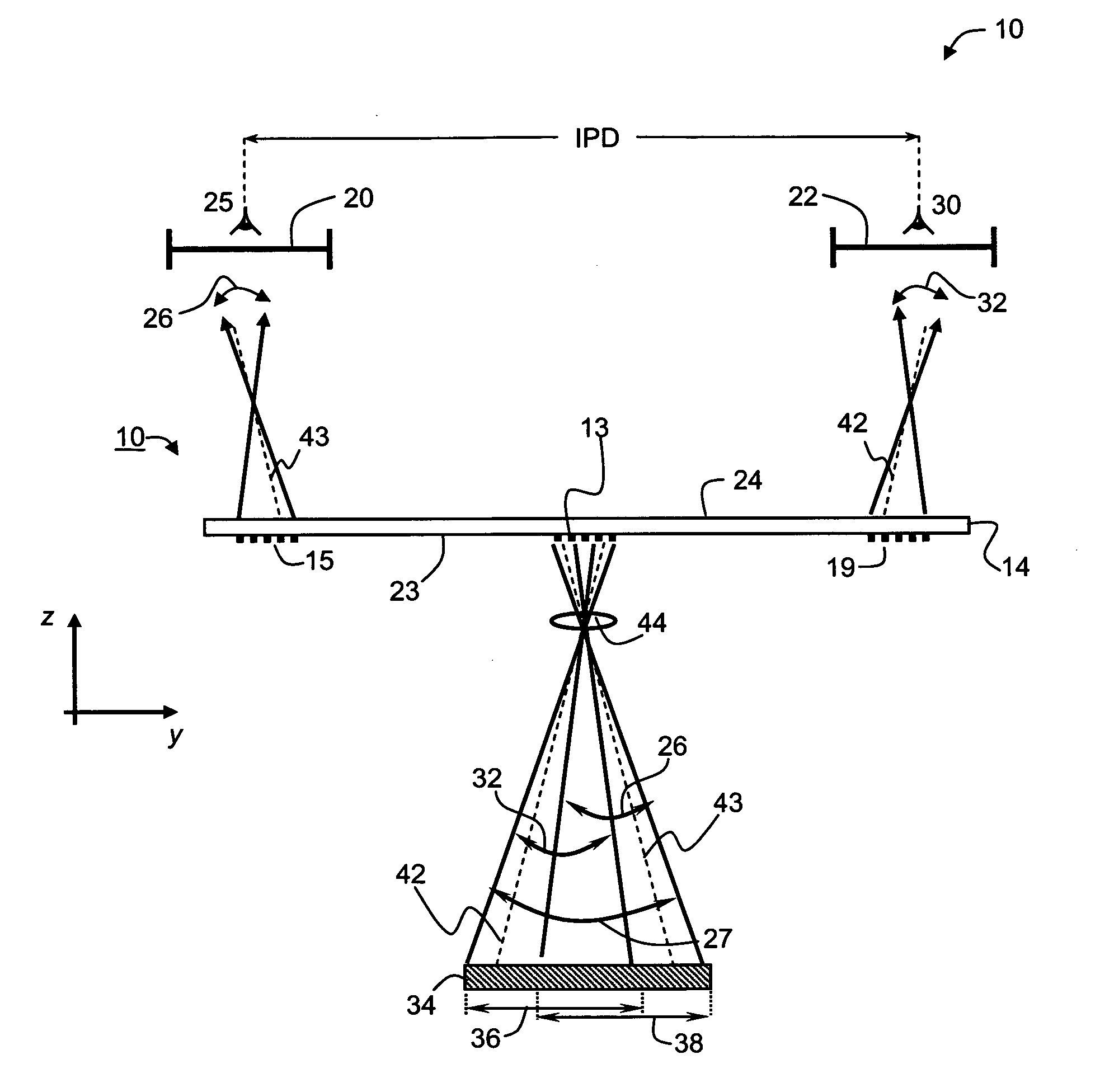
[0057]The present embodiments comprise system, device and method which can be used providing virtual images. Specifically the present embodiments can be used for providing stereoscopic vision of a three-dimensional scene to the eyes of the user.

[0058]The principles and operation of the optical system according to the present invention may be better understood with reference to the drawings and accompanying descriptions.

[0059]Before explaining at least one embodiment of the invention in detail, it is to be understood that the invention is not limited in its application to the details of construction and the arrangement of the components set forth in the following description or illustrated in the drawings. The invention is capable of other embodiments or of being practiced or carried out in various ways. Also, it is to be understood that the phraseology and terminology employed herein is for the purpose of description and should not be regarded as limiting.

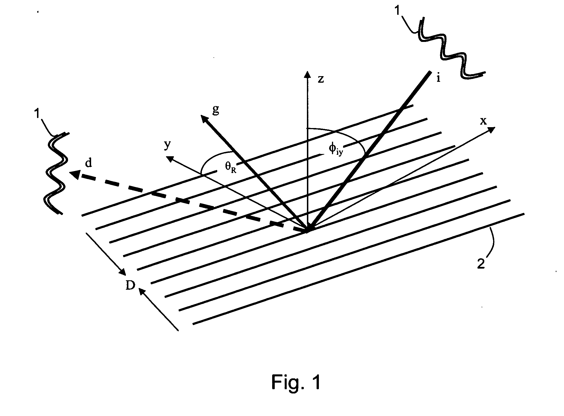
[0060]When a ray of light m...


PUM


Abstract

An optical system for transmitting a stereoscopic image to a right eye and a left eye of a user is disclosed. The system comprises an optical relay device, having a light-transmissive substrate, an input grating, a left output grating and a right output grating. The optical relay device is designed and constructed such that light is diffracted by the input grating, propagates within the light-transmissive substrate via total internal reflection, and diffracted out of the light-transmissive substrate by at least one of the left and right output gratings. The system further comprises an image generating system, optically coupled to the input grating and configured for providing collimated light constituting a left-eye image and a right-eye image wherein the left-eye image is parallactically related to the right-eye image. In various exemplary embodiments of the invention the left-eye image and the right-eye image are spectrally modulated according to different spectral maps, selected to provide different optical information to different eyes.

Description

FIELD AND BACKGROUND OF THE INVENTION[0001]The present invention relates to optics, and, more particularly, to a stereoscopic binocular system, device and method.[0002]A viewer of a two-dimensional image perceives a structure such as depth, thickness or the like, when the two-eyes of the viewer see slightly different images of a three-dimensional scene. The brain of the viewer transforms the different images viewed by the left eye and right eye into information relating to the third dimension of the image, and the image appears to be “three-dimensional”. A technique in which such structures are visually understood is known as stereoscopy.[0003]Stereoscopic displays are largely demanded in many fields, including, virtual reality simulation, telecommunication, entertainment, structure designed, medical imaging and the like. Hitherto, various kinds of studies and developments have been executed with respect to a display which can stereoscopically present an image. Generally, an electro...

Claims


Application Information

Patent Timeline
IPC IPC(8): G02B27/22
CPCG02B5/1814G02B5/30G02B6/00G02B6/005G02B6/124G02B27/0081H04N13/044G02B27/2242G02B27/2264G02B2027/0116G02B2027/0132G02B2027/0134G02B27/0101G02B30/24G02B30/36H04N13/344
Inventor LANDA, BENZIONNIV, YEHUDA
Owner MIRAGE INNOVATIONS
Why Eureka
Try Eureka