Method and network device for realizing shared mesh protection

Active Publication Date: 2010-09-16
HUAWEI TECH CO LTD
View PDF21 Cites 22 Cited by
  • Summary
  • Abstract
  • Description
  • Claims
  • Application Information

AI Technical Summary

Benefits of technology

[0025]Compared with the prior art, in the embodiments of the present disclosure, by adjusting the shared protection bandwidth after protection switching or using the protection LSP as a transition and establishing a new LSP for protection switching, dynamic management and maintenance of the shared protection bandwidth o

Problems solved by technology

In fact, in most cases, a probability of multiple faults occurring at the same time is quite low.
However, the first and second methods of the prior art only support the protection switching for a single fault.
If a second fault occurs before a first fault is recovered (i.e., as available bandwidth information on the protection LSP has been changed after the first fault switching and the system lacks in managing and maintaining the shared protection bandwidt

Method used


Image

  • Method and network device for realizing shared mesh protection
  • Method and network device for realizing shared mesh protection
  • Method and network device for realizing shared mesh protection

Examples


embodiment 1

[0042]When a fault occurs to a working LSP and protection switching is performed, a reserved service bandwidth corresponding to the working LSP is occupied in a shared protection bandwidth on a link of a protection LSP corresponding to the working LSP. Thereby, in the first embodiment, the present disclosure provides a technical solution to protect against subsequent faults by dynamically increasing the shared protection bandwidth of the protection LSP.

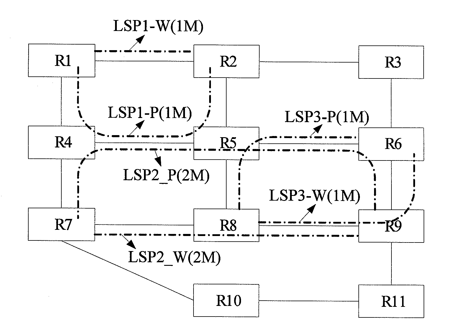
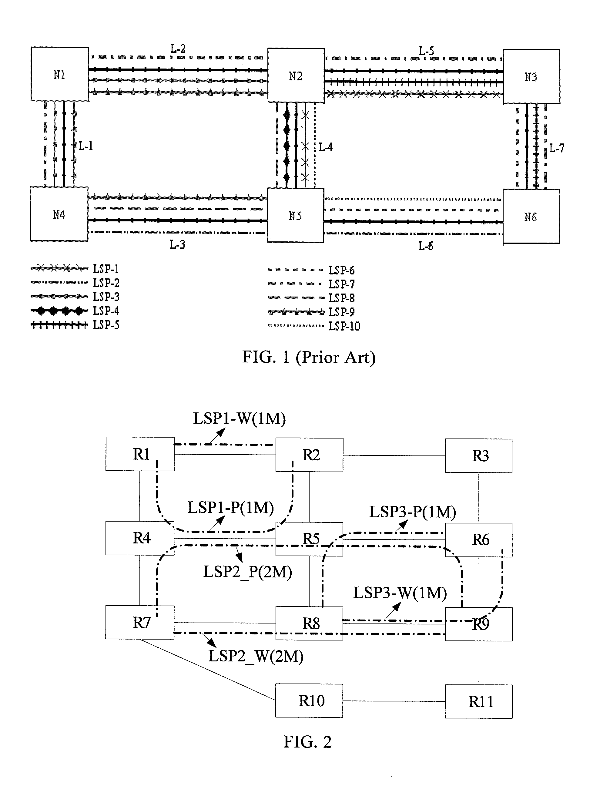
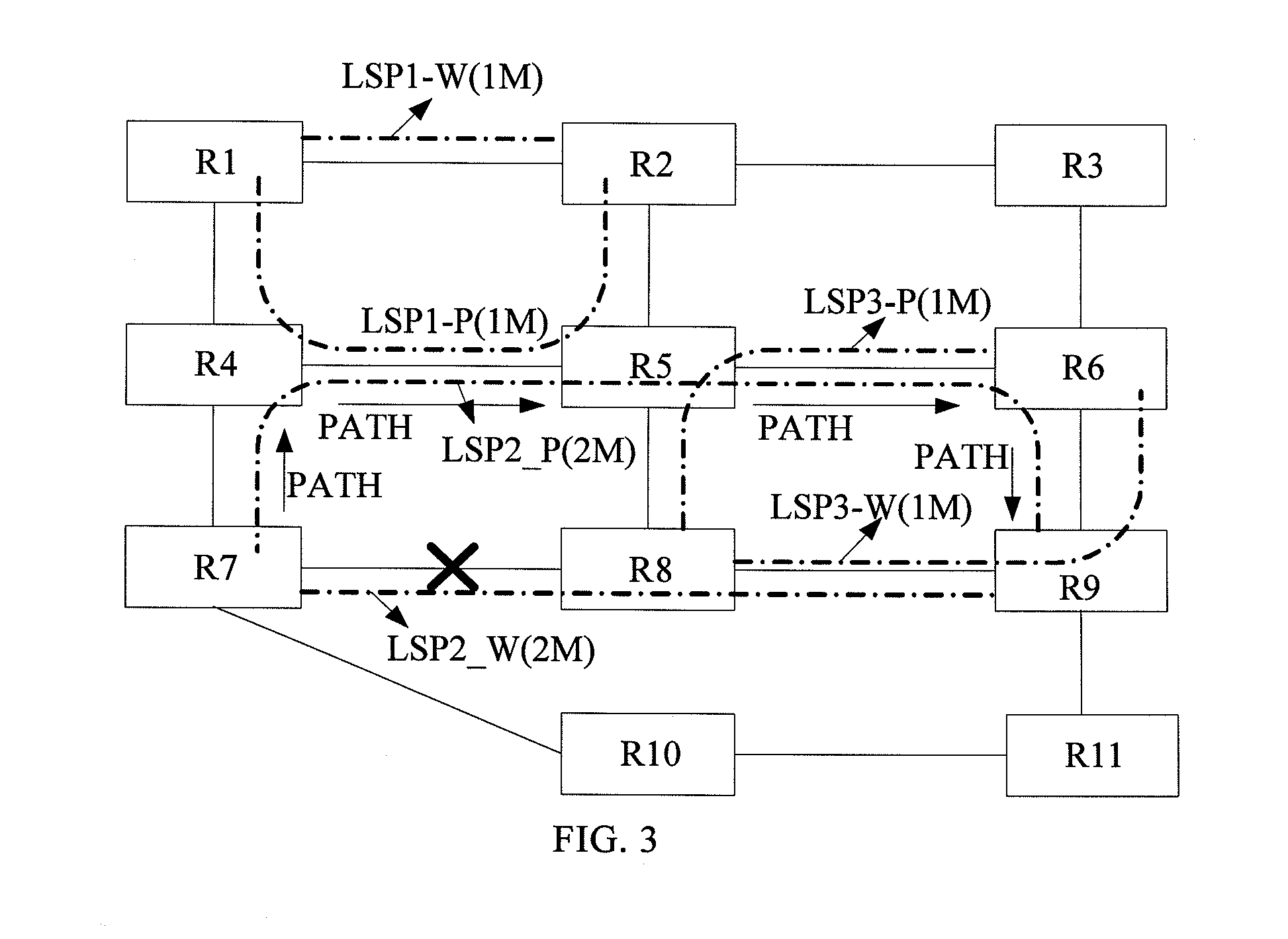
[0043]For example, it is assumed that a fault occurs to link R7-R8 in the network of FIG. 2, as shown in FIG. 3. According to the solution of the first embodiment, a protection switching process implemented after the fault occurs is shown in FIG. 4, which includes the following steps described below.

[0044]In step 401, on a data plane, after node(s) R7 and / or R9 detect that a fault occurs to an LSP2-W through an OAM mechanism, nodes R7 and R9 switch services on LSP2-W to LSP2-P by an automatic protection switching (APS) protocol, so as...

embodiment 2

[0050]After a working LSP is recovered from a fault state to a normal state, services need to be switched from a protection LSP back to the working LSP. A part of a reserved service bandwidth occupied in a link corresponding to the protection LSP is again recovered to a part of a shared protection bandwidth. In the second embodiment, the present disclosure provides a technical solution to protect against subsequent faults by dynamically adjusting the shared protection bandwidth of the protection LSP.

[0051]Specifically, after the protection switching, if the fault in the R7-R8 in FIG. 2 is recovered, the process in FIG. 6 is performed which includes the following steps described below.

[0052]In step 601, on a data plane, after node(s) R7 and / or R9 detect that a fault occurring to an LSP2-W is recovered through an OAM mechanism, nodes R7 and R9 utilize an APS protocol to switch services from an LSP2-P back to the LSP2-W. After the switching is finished, reports are submitted to the con...

embodiment 3

[0058]In the solution provided by the third embodiment of the present disclosure, a current protection path serves as an intermediate transition. When a fault occurs, services are first switched to the current protection path and a new working path is established. Then, the services are switched to the new working path, and the previous protection path is adapted to protect the new working path.

[0059]It is still assumed that a fault occurs to the link R7-R8 in the network shown in FIG. 2, and the protection switching process in the solution according to the third embodiment is implemented as shown in FIG. 7, which includes the following steps.

[0060]In step 701, on a data plane, after node(s) R7 and / or R9 detect that a fault occurs to an LSP2-W through an OAM mechanism, nodes R7 and R9 on the LSP2-W utilize an APS protocol to switch services on the LSP2-W to an LSP2-P, so as to ensure normal operation of the services.

[0061]In step 702, after the switching is finished, the node(s) R7 ...


PUM


Abstract

A method and a network device for realizing shared mesh protection are provided. The method includes the following steps. If a status change of a working label switching path (LSP) is detected, routing information and bandwidth information about the working LSP are notified to every node on a protection LSP corresponding to the working LSP. Every node on the protection LSP calculates a maximal reserved bandwidth of a link based on the received routing information and bandwidth information and adjusts a shared protection bandwidth of the link according to the maximal reserved bandwidth.

Description

CROSS-REFERENCE TO RELATED APPLICATIONS[0001]This application is a continuation of International Application No. PCT / CN2008 / 073623, filed on Dec. 19, 2008, which claims priorities to Chinese Patent Application No. 200710306902.8, filed on Dec. 27, 2007 and Chinese Patent Application No. 200810002355.9, filed on Jan. 15, 2008, all of which are hereby incorporated by reference in their entireties.FIELD OF THE TECHNOLOGY[0002]The present disclosure relates to the field of network protection switching technology, and particularly to a method and a network device for realizing shared mesh protection.BACKGROUND OF THE DISCLOSURE[0003]Network protection is an important characteristic of a telecommunication network. In order to realize the protection, a protection path, not joint (i.e., distinct from) with a working path, is usually established in advance. When a fault occurs to the working path, a working flow is switched from the working path to the protection path. Generally, a protectio...

Claims


Application Information

Patent Timeline
IPC IPC(8): H04L12/26H04L45/02H04L45/125H04L45/24H04L45/28H04L45/50
CPCH04L45/02H04L45/028H04L45/125H04L43/0817H04L45/28H04L45/50H04L45/22
Inventor LONG, HAODONG, JIXIONG
Owner HUAWEI TECH CO LTD
Why Eureka
Try Eureka