Automated power control to optimize power consumption and improved wireless connection

a power consumption optimization and automatic technology, applied in power management, transmission monitoring, wireless communication, etc., can solve the problems of reducing the end-to-end performance, increasing latency, and increasing communication overhead, so as to improve signal sensitivity, improve signal communication quality, and save power best effor

Active Publication Date: 2010-09-16
MINEBEAMITSUMI INC
View PDF4 Cites 66 Cited by
  • Summary
  • Abstract
  • Description
  • Claims
  • Application Information

AI Technical Summary

Benefits of technology

[0010]Many benefits can be achieved through the application of embodiments of the present invention. The power amplifier and low noise amplifier (PA/LNA) circuit added between a Balun port of a ZigBee module (e.g., CC2430 provided by Texas Instrument) transmitter/receiver and its wireless antenna can provide additional power adjustment for the module. In an embodiment, using the PA/LNA circuit for power adjustment can be achieved by switching on the PA connection associated with the ZigBee for transmitting or turning off the PA simply via a bypass circuit using one or two RF switches. In another embodiment, the same ZigBee module with the PA/LNA circuit can receive the signal with enhance...

Problems solved by technology

However, the mesh topology also has several draw backs.
For example, it has higher communication overhead associated with increased latency and lower end-to-end performance compared to other type of networking topo...

Method used


Image

  • Automated power control to optimize power consumption and improved wireless connection
  • Automated power control to optimize power consumption and improved wireless connection
  • Automated power control to optimize power consumption and improved wireless connection

Examples


Embodiment Construction

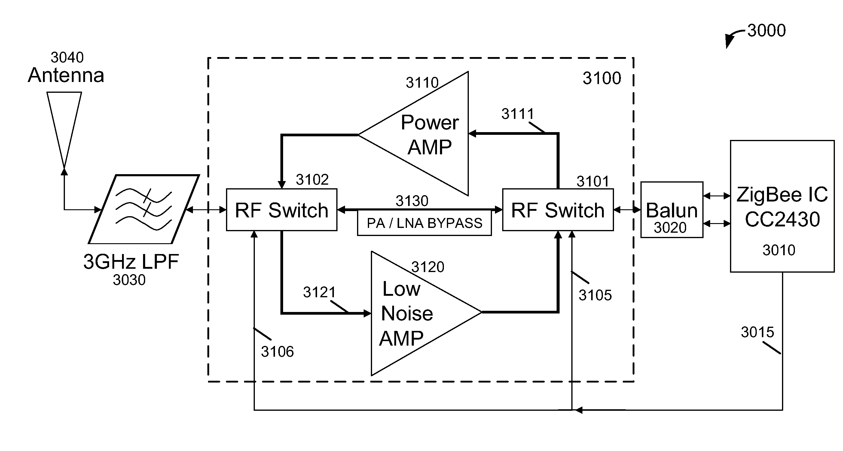
[0018]The invention is directed to a method for automatic output power control of signal transmission between two wireless network module. Merely by way of example, the invention has been applied to control signal output power for a ZigBee networking module with optimized power consumption and improved wireless connection. But it would be recognized that the invention has a much broader range of applicability.

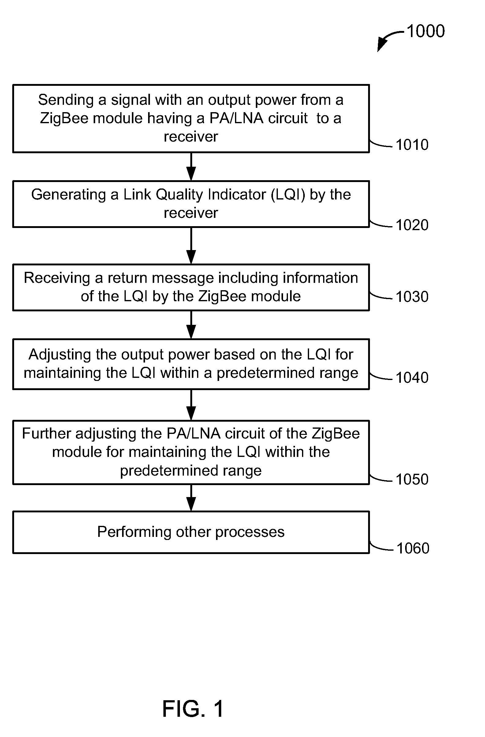
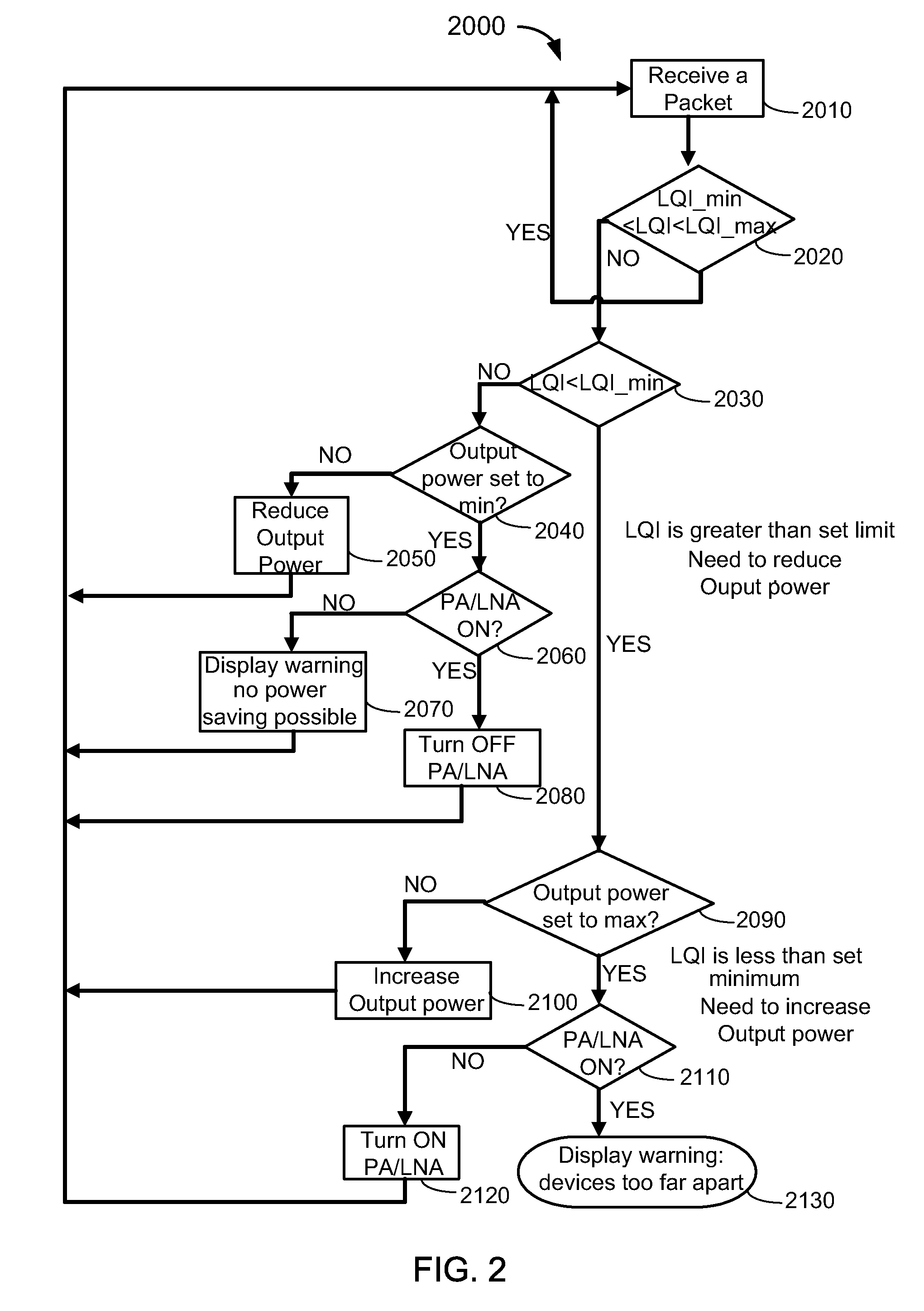
[0019]FIG. 1 is a simplified flowchart illustrating a method for automatically adjusting signal output power of a ZigBee module according to an embodiment of the present invention. This diagram is merely an example, which should not unduly limit the scope of the claims herein. The method 1000 includes the following steps:

[0020]1. Step 1010 for sending a signal with an output power from a ZigBee module having a PA / LNA circuit to a receiver;

[0021]2. Step 1020 for generating a Link Quality Indicator (LQI) by the receiver;

[0022]3. Step 1030 for receiving a return message including ...


PUM


Abstract

A method for automatically adjusting signal output power of a ZigBee wireless module. The method includes sending a signal with an output power from a transmitter of a ZigBee module to a receiver. The ZigBee module includes a power amplifier/low noise amplifier (PA/LNA) circuit. The output power can be adjusted between a minimum level and a maximum level. Additionally, the method includes generating a Link Quality Indicator (LQI) by the receiver based on the signal strength and returning the LQI to the ZigBee module. If the LQI is not within a predetermined range between a maximum value and a minimum value, the method includes adjusting the output power for sending next signal. If the output power from the transmitter has reached to the minimum level or the maximum level, the method further includes adjusting the PA/LNA circuit of the ZigBee module for maintaining the LQI within the predetermined range.

Description

BACKGROUND OF THE INVENTION[0001]The invention is directed to a method for automatic output power control of signal transmission between two network modules. Merely by way of example, the invention has been applied to control signal output power for a ZigBee module with optimized power consumption and improved wireless connection. But it would be recognized that the invention has a much broader range of applicability.[0002]In networking communication application where a signal is sent out from a transmitter to a receiver, it is generally preferred that the transmitter is able to send the signal with an optimum output power so that the signal is sent with substantial power saving while having still sufficient strength at the receiver side to make a successful communication with an expected or valid quality. Especially for wireless technology, power saving would be an important concern for many field applications because most of field-deployed wireless modules are just powered by non-...

Claims


Application Information

Patent Timeline
IPC IPC(8): H04B17/00H04B1/04
CPCH04W52/52
Inventor WU, MARIONAKAYAMA, MAKOTOGUO, JOHNLIENG, JACKLEE, WALTER
Owner MINEBEAMITSUMI INC
Why Eureka
Try Eureka